All published articles of this journal are available on ScienceDirect.

Influence of Support Specific Surface Area and Preparation Method on the Performance of Ru/SiO2 Catalysts for Biphenyl Hydrogenation to Bicyclohexane
Abstract
Introduction
Hydrogen energy is a promising alternative to fossil fuels, yet its storage and transportation remain challenging due to flammability and low density. Liquid organic hydrogen carriers (LOHCs), such as bicyclohexane (BCH) derived from biphenyl (BP) hydrogenation, offer high hydrogen storage density and safety. This study investigates the impacts of support specific surface area (SSA) and preparation methods on the performance of Ru/SiO2 catalysts in BP hydrogenation to BCH.
Methods
Ru/SiO2 catalysts with varying SSA were prepared using the strong electrostatic adsorption (SEA) and incipient wetness impregnation (IWI) methods with [Ru(NH3)6]Cl3 as the precursor and fumed SiO2 as the support. The catalysts were characterized using ICP-AES, XRD, N2 physisorption, H2-TPR, XPS, TEM, and HAADF-STEM. The catalytic performance was evaluated in a high-pressure autoclave under mild conditions (90 °C, 1.0 MPa H2, 80 min) with product analysis conducted using GC-MS.
Results
The 1.5 wt.% Ru/SiO2-SEA (300) catalyst exhibited the best performance, achieving 99.9% BP conversion and BCH selectivity. This catalyst featured smaller Ru nanoparticles (average size 0.91 nm) and stronger metal-support interaction compared to the IWI-prepared catalysts. As the SSA of the SiO2 support increased, the hydrogenation performance improved.
Discussion
The research reveals that SiO2 with high SSA can provide a greater number of active sites, thereby facilitating contact between reactants and the catalyst surface. This enhancement leads to improved catalytic activity and selectivity. Furthermore, the SEA method, which adjusts the solution pH, enables the uniform adsorption of metal ions onto the support surface through electrostatic interactions. This results in smaller Ru nanoparticle sizes and higher dispersion, significantly strengthening the metal-support interaction.
Conclusion
The study highlighted the efficiency of the SEA method in developing the high-performance Ru/SiO2 catalyst for BP hydrogenation. Higher SSA supports, particularly those prepared via SEA, yielded smaller Ru nanoparticles and enhanced dispersion, resulting in superior catalytic activity and selectivity. These findings offered some critical insights for advancing LOHC technology and hydrogen storage applications.
1. INTRODUCTION
With the global population growth and economic development, the energy demand continues to increase dramatically. The over-reliance on fossil fuels leads to the massive emission of greenhouse gases, which causes exacerbated climate change and energy crisis [1]. On that account, both the academic and the industrial worlds are committed to exploring the clean and sustainable energy sources [2]. Therein, hydrogen energy is considered to be one of the most promising renewable energy sources due to its excellent characteristics, such as abundant reserves, high efficiency, non-pollution, high calorific value of combustion, and high energy density [3, 4]. However, the storage and transportation of hydrogen are major technological bottlenecks for its large-scale application due to its extremely flammable and explosive properties [5].
Compared with traditional hydrogen storage systems (high-pressure gaseous storage cryogenic liquid storage metal hydride storage and carbon-based adsorption storage, liquid organic hydrogen carriers (LOHCs) exhibit high reversibility in hydrogenation and dehydrogenation reactions, which significantly enhances the cyclic stability and economic efficiency of hydrogen storage systems [6-10]. With advantages such as high hydrogen storage density, excellent safety, and low cost, LOHCs enable efficient hydrogen storage and transport under ambient conditions, thereby reducing the risks and energy consumption associated with high-pressure or cryogenic storage [11, 12]. These characteristics make LOHCs an effective solution for the safe storage and efficient transportation of hydrogen energy.
Bicyclohexane (BCH) is a novel LOHC prepared by the hydrogenation of biphenyl (BP), and it has significant advantages in hydrogen storage and utilization [13]. On one hand, BCH possesses a high theoretical hydrogen storage capacity up to 7.3 wt.% which is superior to that of the traditional LOHCs (e.g., cyclohexane methylcyclohexane decahydronaphthalene perhydro-dibenzyl-toluene [14-22]. On the other hand, BCH exhibits low volatility and high resistance to decomposition under ambient temperature and pressure, making it suitable for long-term storage and long-distance transportation. The available studies have shown that BCH could be stably stored at room temperature for several months without significant hydrogen loss [23-25]. Additionally, the hydrogenation and dehydrogenation processes of BCH do not produce harmful by-products. Both BP and BCH are low-toxic substances, demonstrating significant environmental friendliness.
When BP is hydrogenated to form BCH, the aromatic structure of BP presents a significant barrier to hydrogenation. This necessitates an effective catalytic system to lower the activation energy, accelerate the reaction, and enhance the selectivity. Supported catalysts, which disperse active metal components on a support surface, significantly increase the specific surface area (SSA) and number of active sites, thereby improving reaction efficiency [26]. Among these, Ru-based catalyst is one of the most promising candidates for the catalytic hydrogenation reactions due to its high activity even under mild conditions [27-29]. The traditional incipient wetness impregnation (IWI) method, despite its simplicity, often results in insufficient catalytic activity due to metal agglomeration [30]. The strong electrostatic adsorption (SEA) method is an efficient approach to prepare the supported catalysts. By adjusting the solution's pH to impart specific charges to the support surface, the metal ions are adsorbed with the opposite charges through the electrostatic interaction [31-33]. It results in a uniform distribution of metal species on the support surface. Compared to the traditional methods, SEA-synthesized catalysts exhibit smaller metal nanoparticle sizes and better dispersion, significantly enhancing catalytic activity [32].
The support disperses the metal active components uniformly to control the size and morphology of the catalyst, and its structural properties (such as SSA and pore structure) significantly affect the catalyst's activity, selectivity, and stability [34]. SiO2 is a commonly used catalyst support due to its high SSA and strong adsorption capacity [35, 36]. These properties make it an effective support for enhancing catalytic activity and reducing costs. Taking the Ru/SiO2 catalyst as an example, an increase in the SSA of SiO2 enlarges the contact area between Ru nanoparticles and the support. This leads to a more uniform distribution of Ru atoms, which in turn accelerates the adsorption and activation of reactant molecules on the catalyst surface. Based on these findings, this study employed SEA and IWI methods to prepare a series of 1.5 wt.% Ru/SiO2 catalysts with varying SSA [37]. The catalytic performance of these catalysts in the hydrogenation of BP to produce BCH was also systematically investigated.
2. MATERIALS AND METHODS
2.1. Catalyst Preparation
A series of Ru/SiO2 catalysts with different SSA were synthesized by the SEA and IMI using [Ru(NH3)6]Cl3 (purity 99.0%, Alfa Aesa Chemical Co., Ltd) as the precursor and fumed SiO2 (purity 99.0%, Aladdin Biochemical Technology Co., Ltd) as the support. The detailed procedures were described as follows:
2.1.1. SEA
Taking 1.5 wt.% Ru/SiO2-SEA (100) as an example. First, 1.0 g of [Ru(NH3)6]Cl3 metal precursor solution was diluted to 100 mL with secondary distilled water, and the pH of the solution was adjusted to 11.5 using ammonia water (NH3·H2O, 25.0~28.0 wt.%, Luoyang Chemical Reagent Factory). Subsequently, 1.0 g of the fumed SiO2 support with the SSA of 100 m2·g−1 was added, and the mixture was continuously stirred at room temperature for 1 hour. After the reaction, the gel-like substance was obtained by centrifugation and washed with secondary distilled water. The resulting material was dried at 60 °C for 24 h, followed by calcination at 120 °C for 4 h to obliterate moisture. Finally, the sample was reduced in a tube furnace at 400 °C for 2 h using 10 vol.% H2/N2 as the reducing gas, yielding a SiO2-supported Ru catalyst with the SSA of 100 m2·g−1, designated as 1.5 wt.% Ru/SiO2-SEA (100). The preparation methods for 1.5 wt.% Ru/SiO2-SEA (200) and 1.5 wt.% Ru/SiO2-SEA (300) were identical to the above steps, except for the SSA of the SiO2 support used.
2.1.2. IWI
Exemplified by the preparation of 1.5 wt.% Ru/SiO2-IWI (100). Initially, 1.0 g of the fumed SiO2 support with the SSA of 100 m2·g−1 was precisely weighed and placed in a crucible, which was then secured on a vortex mixer. The [Ru(NH3)6]Cl3 metal precursor solution was subsequently added dropwise to the carrier using a pipette, accompanied by continuous stirring with a glass rod, until the support completely transformed into a paste-like state, indicating that the support's water absorption had reached saturation, with a volume of 1.5 mL of the precursor solution added. The sample was then subjected to drying, calcination, and reduction processes, adhering to the same protocol as the SEA, culminating in the synthesis of the 1.5 wt.% Ru/SiO2-IWI (100) catalyst. The methodologies for preparing 1.5 wt.% Ru/SiO2-IWI (200) and 1.5 wt.% Ru/SiO2-IWI (300) were consistent with the steps above, differing solely in the SSA of the SiO2 support utilized.
2.2. Catalyst Characterization
2.2.1. Inductively Coupled Plasma-Atomic Emission Spectrometry (ICP-AES)
The actual loading amount of Ru in the employed catalysts was determined by the ICPE-9820 ICP-AES instrument (Shimadzu Corporation, Japan).
2.2.2. X-ray Diffraction (XRD)
The phase composition and crystal structure of the catalysts were examined using a Bruker D8 diffractometer (PANalytical B.V., Netherlands). The characterization was performed with a Cu Kα radiation source (λ = 0.15418 nm), operating at a tube voltage of 40 kV and a current of 40 mA. The scanning rate was set at 0.03 ° s-1, and the diffraction angle range was scanned from 10 ° to 80 °. The diffraction data were analyzed for phase identification using Highscore software, and the diffraction peaks were assigned by comparison with standard reference cards.
2.2.3. N2 Physisorption
The SSA of the materials was analyzed using an ASAP 2420 physisorption analyzer (Micromeritics Instrument Corporation, USA). Prior to the measurements, approximately 100 mg of the fumed SiO2 support and the synthesized catalysts were degassed under vacuum at 150 °C for 180 min. N2 adsorption-desorption isotherms were collected at -196 °C. The SSA was calculated using the Brunauer-Emmett-Teller (BET) method, while the pore volume and pore size distribution were determined using the Barrett-Joyner-Halenda (BJH) method.
2.2.4. H2 temperature programmed reduction (H2-TPR)
The instrument used in this study was the Autosorb-IQ (Quantachrome Instruments, USA) automated gas sorption analyzer, which was coupled with a Pfeiffer Vacuum QME220 mass spectrometer (Pfeiffer Vacuum, Germany). Approximately 50 mg of the sample was heated in an argon atmosphere (25°C to 200 °C at a rate of 10 °C·min−1), purged for 40 min, and then cooled to 40°C. A mixture of 10 vol.% H2/Ar (flow rate: 40 mL·min−1) was introduced and purged for 15 min, while the signal was monitored using the TCD until the baseline stabilized. The temperature was then increased from 40 °C to 400 °C at a heating rate of 10 °C·min-1, and the signal was continuously recorded to obtain the reduction profile of the sample.
2.2.5. X-ray photoelectron spectroscopy (XPS)
The surface composition and electronic states of the catalyst were analyzed using a Quantera SXM XPS instrument (Ulvac-Phi., Japan). The measurements were conducted under ultra-high vacuum (109 Torr) with an Al Kα source (hν = 1486.6 eV) as the excitation source. Charge correction was performed using the C 1s peak (284.8 eV) binding energy as the reference. The data were fitted using XPS Peak41 software. During the fitting process, the spin-orbit splitting value of Ru 3d was set to 4.2 eV, and the area ratio of the Ru 3d5/2 to Ru 3d3/2 doublet peaks was fixed at 3:2, with equal peak widths. All samples were subjected to a reduction pretreatment under a H2/Ar atmosphere prior to measurement.
2.2.6. Transmission electron microscopy (TEM) and High-angle annular dark-field scanning transmission electron microscopy (HAADF-STEM)
The morphology and structure of the catalyst, as well as the size distribution of metal Nanoparticles, were characterized using a Tecnai G2 F20 transmission electron microscope operating at 200 kV (FEI Company, USA).
2.3. Catalytic Activity Evaluation
The hydrogenation reaction of BP was conducted in a high-pressure autoclave (YZQR-100M). A mixture containing 0.13 g of catalyst, 1.54 g of BP (C12H10, purity 98.0%, Sinopharm Chemical Reagent Co., Ltd), and 45 mL of isopropanol (C3H8O, purity 99.0%, Fengchuan Chemical Reagent Technology Co., Ltd) was added to the reactor, which was then sealed. The air inside the reactor was purged three times with hydrogen until the pressure gauge indicated 1.0 MPa. The reaction conditions were set as follows: a reaction temperature of 90 °C, a stirring speed of 500 rpm, and a reaction time of 80 min. Stirring was initiated, and once the desired reaction temperature was reached, the hydrogen inlet valve was opened to introduce the required reaction pressure of 1.0 MPa. After the reaction was completed, the hydrogen inlet valve was closed, and the system was cooled to room temperature. The pressure was then slowly released to atmospheric pressure.
The reaction products were analyzed using a high-pressure pyrolysis-gas chromatography-mass spectrometry system (GCMS-QP2010 SE, Shimadzu Corporation, Japan) equipped with an SH-RXI-5SIL-MS column (30 m × 0.25 mm × 0.25 µm) and a flame ionization detector (FID). The initial temperature of the oven was set at 70 °C and increased to 280 °C at the heating rate of 20 °C·min-1 (held for 2 min). At the same time, the temperatures of the injector and FID were set to 260 °C and 270 °C, respectively [37].
The products were analyzed using the area normalization method. The conversion of BP and the selectivity of BCH were calculated using the following Eqs. (2.1 and 2.2):
 |
(2.1) |
 |
(2.2) |
where, C0 represented the initial concentration of BP in the reaction system at the start of the reaction (mol·L-1), Ct was the concentration of BP in the reaction system at a reaction time of t (mol·L-1), CBCH was the concentration of BCH in the reaction system at a reaction time of t (mol·L-1).
3. RESULTS AND DISCUSSION
Table 1 shows the textural parameters of the Ru/SiO2 catalysts synthesized using the SEA and IWI methods with SiO2 supports of varying SSA. In the case of using a fumed SiO2 support with an SSA of 100 m2·g-1, the SSA of the 1.5 wt.% Ru/SiO2 catalysts synthesized by the SEA and IWI methods was 194.4 m2·g-1 and 209.7 m2·g-1, respectively, both significantly higher than the SSA of the SiO2 support itself (100 m2·g-1). This may be attributed to the fact that when the specific surface area (SSA) of SiO2 is relatively low, a portion of the Ru metal is deposited on the surface of the carrier, which alters the pore structure of the carrier to some extent, thereby leading to an increase in the SSA. Notably, the catalyst synthesized by the IWI method exhibited a higher SSA (209.7 m2·g-1) compared to that synthesized by the SEA method (194.4 m2·g-1). When supports with SSA of 200 m2·g-1and 300 m2·g-1 was used, the SSA of the resulting catalysts were lower than those of the corresponding SiO2 supports, with the SEA method yielding catalysts with SSA of 179.6 m2·g-1 and 218.3 m2·g-1, respectively, which were lower than those synthesized by the IWI method (190.5 m2·g-1 and 245.0 m2·g-1). Furthermore, under similar preparation conditions, catalysts synthesized by the SEA method generally had larger pore diameters, while those synthesized by the IWI method had higher pore volumes. This indicates that the catalysts synthesized by the SEA method on a SiO2 support with an SSA of 300 m2·g-1 possess highly dispersed and well-exposed Ru nanoparticles.
Furthermore, the dispersion of the catalysts was determined by CO chemisorption. The results indicated that the dispersion of the catalysts prepared by the SEA method was higher than those prepared by the IWI method. Among them, the 1.5 wt.% Ru/SiO2-SEA (300) catalyst exhibited the highest dispersion (11.4%), which corresponds to its smaller Ru nanoparticle size and higher specific surface area (218.3 m2·g-1). This high dispersion of Ru particles provides more active sites for the catalytic reaction, thereby enhancing the catalytic performance. Based on the dispersion, the TOF value for this catalyst was calculated to be 4081.74 h-1, significantly higher than that of the 1.5 wt.% Ru/SiO2-IWI (300) catalyst, which was 1940.91 h-1. This result suggests that the catalyst prepared by the SEA method has a stronger metal-support interaction.
Fig. (1) shows the N2 adsorption/desorption isotherms and pore size distribution curves of Ru/SiO2 catalysts prepared by the SEA and IWI methods with the varied SSA. Fig. (1a and 1c) show that all samples exhibit type IV isotherms with H3 hysteresis loops [38], indicating that the Ru/SiO2 catalysts are rich in mesoporous structures, which are advantageous for catalytic reactions. In conjunction with Table 1, Fig. (1b and 1d), it is evident that the pore diameters of the 1.5 wt.% Ru/SiO2-SEA (300) (19.40 nm) and 1.5 wt.% Ru/SiO2-IWI (300) catalysts (18.47 nm) are significantly smaller than those of the corresponding 1.5 wt.% Ru/SiO2-SEA (100), 1.5 wt.% Ru/SiO2-SEA (200), 1.5 wt.% Ru/SiO2-IWI (100), and 1.5 wt.% Ru/SiO2-IWI (200) catalysts (22.02 nm, 25.29 nm, 21.06 nm, and 23.59 nm). This indicates that using SiO2 support with a higher specific surface area (SSA) (300 m2·g-1) is conducive to the formation of catalysts with smaller pore sizes, providing more active sites, thus increasing the contact opportunities between reactants and the catalyst surface, and further enhancing the selectivity and activity of the catalyst [39].
| Entry | Sample | SBET (m2·g-1) | Dispersiona (%) | dpore (nm) | Vpore (cmm3·g-1) |
|---|---|---|---|---|---|
| 1 | 1.5 wt.% Ru/SiO2-SEA (100) | 194.4 | 7.9 | 22.02 | 1.18 |
| 2 | 1.5 wt.% Ru/SiO2-SEA (200) | 179.6 | 8.8 | 25.29 | 1.22 |
| 3 | 1.5 wt.% Ru/SiO2-SEA (300) | 218.3 | 11.4 | 19.40 | 1.15 |
| 4 | 1.5 wt.% Ru/SiO2-IWI (100) | 209.7 | 1.1 | 21.06 | 1.28 |
| 5 | 1.5 wt.% Ru/SiO2-IWI (200) | 190.5 | 1.3 | 23.59 | 1.24 |
| 6 | 1.5 wt.% Ru/SiO2-IWI (300) | 245.0 | 1.6 | 18.47 | 1.30 |
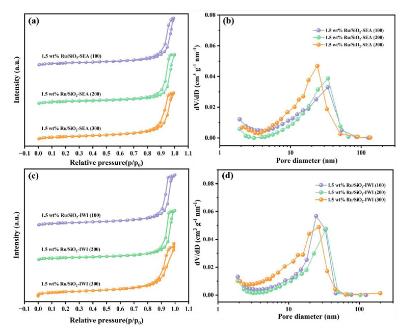
N2 adsorption/desorption isotherms (a) and (c) and pore size distributions (b) and (d) of Ru/SiO2 catalysts synthesized by SEA and IWI.
The regulatory effect of SiO2 with a high specific surface area (300 m2·g-1) on the pore size is derived from its unique hierarchical pore structure (Fig. 1d). The N2 adsorption isotherm indicates that this support has a wide mesoporous distribution ranging from 4 to 30 nm, with approximately 58% of the pores concentrated in the range of 10 to 20 nm. When the SEA method is adopted, [Ru(NH3)6]3+ will selectively adsorb on the inner surface of the pores with a size of 15 to 20 nm [37]. During the subsequent H2 reduction process, the pore walls will restrict the radial growth of Ru crystallites, ultimately forming a uniform pore size of 19.4 nm. This structure enhances the diffusion efficiency of the reactant BP, which directly contributes to the selectivity of 99.9% for BCH.
Fig. (2) presents the XRD patterns of the Ru/SiO2 catalysts synthesized by the SEA and IWI methods with the varied SSA. As shown in Fig. (2a), the catalysts synthesized by the SEA method exhibit a broad diffraction peak at approximately 2θ = 22.0°, corresponding to the SiO2 (111) crystal plane (JCPDS: 89–3433), and no characteristic diffraction peaks of the metallic Ru are observed. However, the catalysts synthesized by the IWI method display diffraction peaks at approximately 2θ = 22.0° for the SiO2 (111) crystal plane, as well as a characteristic diffraction peak at approximately 2θ = 44.0° for the metallic Ru (101) crystal plane (JCPDS: 06–0663) (Fig. 2b). This indicates that the metallic Ru particles in the catalysts synthesized by the SEA method have smaller size and higher dispersion [40]. The pore size distribution in Fig. (1b and 1d), and SSA, pore volume (Vp), and average pore size in Table 1 can favor the formation of highly dispersed Ru particles. Such differences stem from the SEA method's ability to more effectively promote the uniform distribution of Ru precursors on the SiO2 support during the synthesis process, thereby inhibiting the aggregation and growth of Ru particles [41].
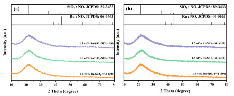
XRD patterns of Ru/SiO2 catalysts synthesized by the SEA (a) and IWI (b) methods.
Fig. (3) presents the transmission electron microscopy (TEM) and high-angle annular dark-field scanning transmission electron microscopy (HAADF-STEM) images along with the particle size distribution histograms of Ru/SiO2 catalysts synthesized by the SEA and IWI methods. The results indicate that catalysts prepared using SiO2 with an SSA of 100 m2·g-1 as the support exhibit larger average particle sizes of metal Ru nanoparticles (Fig. 3a-b, 1.49 nm). In contrast, those prepared using SiO2 with the SSA of 200 and 300 m2·g-1 have smaller average particle sizes (Fig. 3c-d), 1.24 nm and (Fig. 3e-f), 0.91 nm, respectively). This suggests that SiO2 with a larger SSA is more suitable as a support for the supported catalysts. Similarly, the 1.5 wt.% Ru/SiO2-IWI (100) catalyst synthesized by the IWI method has an average particle size of 5.36 nm (Fig. 3g-h), which is significantly larger than that of 1.5 wt.% Ru/SiO2-IWI (200) catalyst (Fig. 3i-j, 4.90 nm) and 1.5 wt.% Ru/SiO2-IWI (300) catalyst (Fig. 3k-l), 3.21 nm). It can be concluded that, compared to the IWI method, the SEA method results in catalysts with smaller metal Ru nanoparticle sizes and a narrower size distribution, consistent with the before mentioned findings. Notably, the catalyst synthesized by the SEA method on SiO2 with an SSA of 300 m2·g-1 has the smallest metal Ru nanoparticle size.
Fig. (4) shows the XPS spectra of the C 1s and Ru 3d regions for Ru/SiO2 catalysts made using the SEA and IWI methods. Because the C 1s and Ru 3d3/2 signal peaks overlap, the Ru 3d5/2 peak was used to study the electronic properties of the Ru species. For the catalysts made by the SEA method. The Ru 3d5/2 peak is observed at 281.4-281.8 eV (Fig. 4a), i.e., at a higher binding energy than 280.2 eV, characteristic of the metallic Ru [42]. This may indicate that the Ru particles have some positive charge, i.e. partially oxidized state, due to interaction with the oxide surface of the SiO2 support. The catalysts made using the IWI method have a Ru 3d5/2 peak at 280.2~280.7 eV (Fig. 4b), characteristic of the metallic form of Ru species. The binding energy of the Ru 3d5/2 peak is much higher for catalysts made using the SEA method compared to those made using the IWI method. This is most likely because the highly dispersed metal Ru nanoparticles have a strong metal-support interaction [43]. The XPS results agree with the XRD and TEM results, which further proves that increasing the support's SSA makes it easier to make Ru/SiO2 catalysts that are smaller and more evenly distributed. This makes the catalysts more active and stable, which leads to better performance in catalytic reactions.
Fig. (5) shows the H2-TPR profiles of Ru/SiO2 catalysts made using the SEA and IWI methods. It shows the desorption signal intensity that was detected as the temperature rises for catalysts made with supports that have different SSAs. The SEA method was used to make catalysts that show different desorption peaks at different temperatures. The low-temperature peaks are caused by the reduction of RuO2 oxides to metallic Ru0, and the high-temperature peaks are caused by the reduction of Ru3+ ions to metallic Ru0 [44]. The desorption peaks shift to higher temperatures with an increase in the SSA [45]. In particular, the 1.5 wt.% Ru/SiO2-SEA (300) shows signs of desorption at 274 °C and 356 °C (Fig. 5a). For the catalysts synthesized by the IWI method, the TPR profiles display only one sharp peak, with the 1.5 wt.% Ru/SiO2-IWI (300) exhibiting an absorption peak at 252 °C. The SEA method produces catalysts with a much larger reduction peak area and higher reduction temperatures compared to the IWI method. This is because the metal-support interaction between the Ru nanoparticles and the SiO2 support is stronger [46].
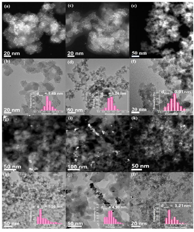
TEM and HAADF-STEM images along with the corresponding particle size distribution histograms of 1.5 wt.% Ru/SiO2 catalysts: (a) and (b) SEA (100), (c) and (d) SEA (200), and (e) and (f) SEA (300); (g) and (h) IWI (100), (i) and (j) IWI (200), and (k) and (l) IWI (300).
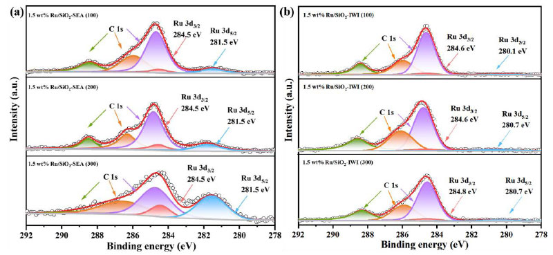
XPS spectra of C 1s and Ru 3d for Ru/SiO2 catalystssynthesized by the SEA (a) and IWI (b) methods.
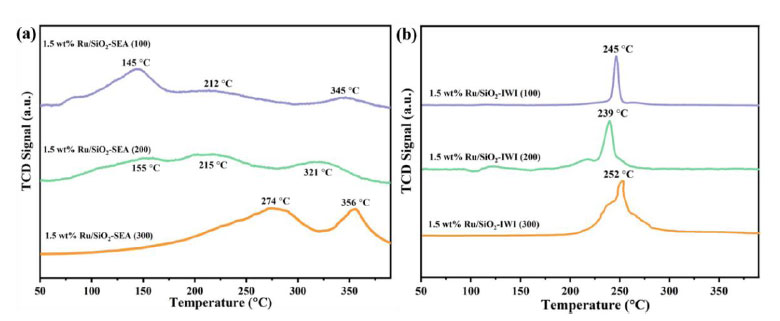
H2-TPR profiles of the Ru/SiO2 catalysts synthesized by theSEA (a) and IWI (b) methods.
It is worth noting that the difference in the intensity of the Ru 3d5/2 peaks between the SEA and IWI catalysts is not only due to the particle size effect (IWI: 5.36 nm vs SEA: 0.91 nm), but also closely related to the spatial distribution of Ru. The SEA method restricts [Ru (NH3)6]3+ to the surface of SiO2 through electrostatic adsorption. The H2-TPR results show that the IWI sample exhibits only a single reduction peak at 252°C (Fig. 5b), indicating that some Ru species are not completely reduced, which is consistent with the weakening of the XPS signal. This surface enrichment characteristic enables the SEA catalyst to expose more active sites, which is directly related to its excellent hydrogenation performance.
The strong metal-support interaction between Ru and SiO2 originates from a multi-scale synergistic mechanism: Firstly, XPS analysis reveals that the binding energy of Ru 3d5/2 in the catalyst prepared by the SEA method shifts positively by 1.6 eV to 281.8 eV (Fig. 4a), confirming that electrons migrate from Ru to the hydroxyl groups on the
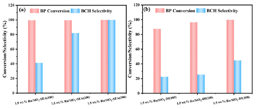
BP hydrogenation performance over the Ru/SiO2 catalysts synthesizedby the SEA (a) and IWI (b) methods. Reaction conditions: 0.13 g of catalyst, 1.54 g of BP, 45 mL of isopropanol, 1.0 MPaof H2, 90 °C, 80 min, and 500 rpm.
surface of SiO2 to form covalent bonds of Ruδ+-O-Si. Secondly, HAADF-STEM directly observes that the Ru nanoparticles and the (111) crystal plane of SiO2 exhibit a lattice matching of 2.3 Å (Fig. 3f). This epitaxial growth mode achieves structural coupling through the Ru-O-Si interface bonds. More importantly, the mesopores with a size of 2-5 nm in the support with a high specific surface area (300 m2·g-1) generate a spatial confinement effect, which not only restricts the size of Ru particles to 0.91 nm, but also enhances the interfacial electron perturbation through the curvature effect. The three factors work synergistically to construct a stable “electron-geometric-spatial” triple interaction system.
(Fig. 6) illustrates the impact of Ru/SiO2 catalysts synthesized by the SEA and IWI methods with different SSAs on the hydrogenation performance of BP. As shown in Fig. (6a), for the catalysts prepared by the SEA method, the BP conversion reaches 99.9%, and the selectivity towards BCH increases with the increase of the support's SSA. Notably, the 1.5 wt.% Ru/SiO2-SEA (300) exhibits both BP conversion and BCH selectivity of 99.9% (Eqs. 2.1 and 2.2). In the case of catalysts synthesized by the IWI method (Fig. 6b), the selectivity of BCH also rises with the increase in the support's SSA, with the 1.5 wt.% Ru/SiO2-IWI (300), achieving a BCH selectivity of 43.9% (Eq. 2.2). Overall, compared to the catalysts synthesized by the IWI method, those prepared by the SEA method demonstrate superior performance in the hydrogenation of BP. The highest hydrogenation activity is observed for the 1.5 wt.% Ru/SiO2-SEA (300), based on the existing characterizations, we speculate that the high selectivity mainly stems from: the ultra-small Ru particle size confirmed by TEM and XPS, together with the electron modification and the confinement effect of the mesopores in SiO2 [37].
CONCLUSION
In summary, a series of Ru/SiO2 catalysts were prepared using the SEA and IWI methods to explore the effects of the support SSA and preparation method on the performance of Ru/SiO2 catalysts in BP hydrogenation. The results indicated that the 1.5 wt.% Ru/SiO2-SEA (300) catalyst, fabricated using the silica support with SSA of 300 m2·g-1 via the SEA method, exhibited the desired structural properties of smaller Ru Nanoparticles (average size of 0.91 nm), higher metal dispersion, and stronger metal-support interaction. As a result, both BP conversion and BCH selectivity reached 99.9%, significantly outperforming the 1.5 wt.% Ru/SiO2-IWI (300) catalyst (average particle size of 3.21 nm, only 43.9% BCH selectivity). Besides, as the specific surface area (SSA) of the SiO2 support increases, the hydrogenation performance of the catalysts for biphenyl improves. For catalysts prepared by the SEA method, the biphenyl conversion remains at a high level (99.9%), while the selectivity to bicyclohexane increases with the increase in SSA. For catalysts prepared by the IWI method, the yield of bicyclohexane increases with the increase in SSA. Overall, the catalyst prepared by the SEA method using SiO2 with an SSA of 300 m2·g-1 as the support exhibited the best catalytic performance, indicating that a higher SSA of the support is more conducive to the dispersion of active components and the progress of the catalytic reaction. This study highlighted the advantages of the SEA method in preparing high-performance Ru/SiO2 catalysts, providing some valuable insights into the development of the catalysts for BP hydrogenation to BCH and the LOHC technology.
AUTHORS' CONTRIBUTIONS
The authors confirm their contribution to the paper asfollows: L.A.: Investigation, Formal Analysis, Data Curation, Writing - Original Draft; W.S.: Validation, Formal Analysis, Investigation, Writing - Original Draft; M.Z.: Conceptualization, Methodology, Resources, Writing - Review & Editing, Supervision, Project Administration. Allauthors reviewed the results and approved the final version of the manuscript.
LIST OF ABBREVIATIONS
| LOHCs | = Liquid Organic Hydrogen Carriers |
| SEA | = Strong Electrostatic Adsorption |
| IWI | = Incipient Wetness Impregnation |
| SSA | = Specific Surface Area |
| BCH | = Bicyclohexane |
| BP | = Biphenyl |
AVAILABILITY OF DATA AND MATERIAL
The data sets used and/or analysed during this study are available from the corresponding author upon request.
ACKNOWLEDGEMENT
Declared none.