All published articles of this journal are available on ScienceDirect.

Flotation of Chromite as Pre-Treatment of Olivine Before Carbonation for CO2 Sequestration
Abstract
Background and Objective:
For the sake of optimal beneficiation of the products formed in the chemical sequestration of CO2 on silicates, extraction of the chromite has been carried out prior to carbonation, by flotation in a lab-scale column.
Method:
Industrial-grade olivine and serpentine were tested. Flow conditions e.g. gas flow rate, stirring, particle diameter of silicates, and physicochemical considerations (composition if the electrolyte solution) have been examined to optimize the separation efficiency in terms of chromite recovery or enrichment factor.
Result:
The high performance observed with chromite-enriched olivine allows a multistage flotation process from low-chromite minerals blends to be designed.
Conclusion:
The lower performance with native olivine was attributed to the existence of mixed chromite-silicate particles.
1. INTRODUCTION
The increasing concentration of CO2 in the atmosphere is attributed to the rising consumption of fossil fuels for energy generation or use around the world. In order to develop steel industry with low carbon dioxide emissions, sequestration process by mineral carbonation can be considered. Olivine has been selected as mineral feedstock because of its large disposal, its reasonable cost and its fair reactivity over 150°C and 20 bars. Serpentine, a hydrated form of olivine can also be considered for carbonation but only after thermal treatment. Olivine is a magnesium-iron silicate (Mg, Fe)2SiO4 that also contains small amounts of other minerals e.g. chromium oxide at concentration levels near 0.2 wt%. Chromium oxide is associated to iron and magnesium in the form of chromite particles which are inert during the carbonation reaction. Sequestration of carbon dioxide is not directly a profitable process if one considers the only tax penalty of CO2 emission, in the order of €15 per ton. As a matter of fact, taking into account the cost of the milled olivine particles, the cost of energy required in compression and heating of the reactants, plus the cost of additional reagents to be added for more complete conversion, carbonation of olivine particles has a cost estimated to range € 80 – 200 per ton CO2 depending on the process considered [1-3], far larger than that of the above CO2 emission. For this purpose, within the Ademe-funded Valorco project in France with ArcelorMittal, it has been decided to investigate thoroughly the separation and purification of the various mineral fractions. The challenge is based on the combination and the coordination of the purification steps within the overall process. Because of nil reactivity of chromite in the carbonation step, it has been decided to extract chromite particles before carbonation, i.e. from olivine particles. The present paper is thus focused on this separation.
Pre-treatment of olivine has been investigated to collect chromite particles before carbonation. Chromite, ideally formed by FeO-Cr2O3 combination, often contains other compounds e.g. magnesia and alumina, depending on its origin. Separation from other minerals or simply from ore gangue, has been largely investigated because of the importance of chromium and ferrochrome markets [4-7]. As explained by Panda et al. [8], various techniques can be considered for the separation depending on the particle sizes. Mechanical operations as magnetic and gravimetric separations are appropriated for particles with a size distribution in the range 50 µm-1 mm [9], but recent advances in technology made it possible to handle 25 µm particles. Based on surface phenomena, flotation and flocculation have been developed to separate finer particles, respectively in the range 25-100 µm [6] and below 20 µm for the latter technique.
After developments from the early 20th century [10]; flotation is now widely used to extract particles dispersed in liquid wastes from various sources e.g. paper manufacture, refineries, deinking operations, metal plating, meat processing, iron and steel plants, chemical processing and manufacturing plants [11-13]. In column systems, the counter-current flow of suspension and gas introduced by a sparger or a venturi, creates an upward transport of the hydrophobic particles by bubbles action [10]. For suitable values of the particle zeta potential, depending on the pH and the composition of the liquid phase, the collector added adsorbs on the surface of the particles to be floated and gives them a hydrophobic behavior by their amphiphilic part. The hydrophobicity of the collector-covered surface allows gas bubbles to adhere on their surface: the floated particles are transferred to the froth, then mechanically dragged out of the system, whereas the gangue – non-floating matter - is discharged as tailings [14] Flotation systems consist of two parts: (i) in the collection zone, the hydrophobic particles attach the bubbles surface, then flow upward towards the free surface of the suspension; (ii) in the rinsing zone, the froth containing the recoverable particles is mechanically collected by overflow. The separation efficiency can be improved by the presence of a depressant, which favors the settling of non-floated particles, thus the separation selectivity, and a frother, whose high surface tension allows the formation of a stable froth on top of the column.
Various collectors have been used for flotation of chromite particles. Chromite is a spinel derived from the FeO-Cr2O3 spinel in which Mg and Al cations partly replace Fe and Cr cations: the composition of the chromite is to exert appreciable influence on the operating conditions of flotation and its efficiency. Apart from dodecylamine employed by Greek scientists [15] for separation of chromite at 3 wt% from olivine particles, organic salts are usually employed as collectors. For positively charged chromite particles, sodium oleate, dodecylsufate or i-butyl xanthate: the two first salts have been used at pH 4 [6] for removal of chromite particles from a liquid waste, whereas butyl xanthate has been suggested in the presence of CuOH+ ions at pH 8.9 [14]. The latter technique has been developed in continuous flotation columns or in other pilot or industrial devices for processing of UG2 ore in South Africa [5, 16-18] to remove the major chromite-containing part of the ore, in view to recovering platinum group elements. Guar gum was added as depressant and polyglycol ethers or alkoxy substituted paraffins usually acted as the frother. For negatively charged surfaces of the minerals, cetyl trimethyl ammonium bromide (CTMAB) has shown its efficiency at pH 4 and pH 11 [6] in a laboratory column for 3 wt% chromite suspensions.
For the present case of olivine, with very low chromite content, it has been preferred to investigate the feasibility of the separation in a discontinuous laboratory flotation column as used in [6] Because of the low chromite content in the olivine stock, the technique has first been developed considering 3 wt.% chromite-enriched olivine, for determination of optimal physicochemical and hydrodynamic conditions. Then the flotation efficiency has been followed depending on the amount of added chromite, from 0% (original olivine) to 20 wt%, in view to evaluating the feasibility of the targeted chromite-free olivine preparation. Based on discontinuous flotation, the strategy is to simulate a continuous circuit to produce chromite with a sufficient purity and/or to purify olivine before carbonation. As a matter of fact, an industrial flotation process can consist in a multi-stage process in which the collected particles on top of one stage is injected into the next one in view to recovering highly concentrated chromite.
2. EXPERIMENTAL SECTION
2.1. Experimental Devices
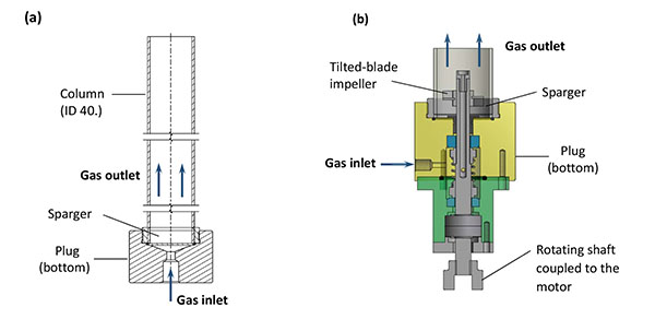
The flotation separation has been carried out at laboratory scale in a discontinuous methyl polymethacrylate 40 mm ID column (Fig. 1a) with a length-over-diameter, L/D, ratio at 15. This ratio is significantly lower than in the continuous columns developed by Xu et al. [19] and used in more recent investigations [4, 18, 20], but the dimensions of the above column are in accordance to those recommended in [6, 21, 22]. The gas bubbles were generated by injection of a nitrogen flow through a sparger fixed at the bottom of the column (Fig. 1a). The sparger was a 40 mm disc of sintered stainless steel (poral, Class 5), whose pore dimensions are suitable for solid-liquid filtration of particles larger than 5.9 µm (> 98%). In a second configuration, a mechanical impeller with a rotation shaft coupled to the column bottom plug (Fig. 1b), has been mounted at the bottom of the above column: the impeller was a four tilted blade device with a diameter of 27 mm. Agitation has been tested in view to promoting the diffusion of collectors to particles and to producing smaller gas bubbles to enhance the probability of bubble-particle collision. Moreover, this more complex technique had been developed to avoid particle settling and to favor flow circulation in the column.
2.2. Chemicals
Sodium hydroxide (in pellets) and sodium hydrogenphtalate were purchased from Sigma Aldrich (BioXtra grade) with a purity over 98 and 99.95% respectively. Cetyl trimethyl ammonium bromide (CTMAB) was also from Sigma Aldrich (> 98%). Sodium hydrogencarbonate (RP, France, Normapur) had a purity larger than 99.5%.
2.3. The Methods Used
2.3.1. Sample Characterization
The particle size distributions have been determined by a Malvern Mastersizer 2000 equipment, for chromite, olivine and serpentine particles. Particle observations by scanning electron microscopy, SEM, coupled to energy-dispersive X-ray spectroscopy, EDX, have been performed using a JEOL Scanning Microscope JSM-6490LV apparatus. EDX measurements for one solid sample was carried out over several particles, and for each particle, five measurements were taken: the values given in the paper are the average over locations and particles, allowing the overall composition of the solid surface to be determined. Care has been taken in calibration of the method by using various (chromite-olivine) blends. For determination of the efficiency of chromite separation by flotation, the results of the elemental analysis by EDX on the collected particles have been examined and compared to those of the solid particles introduced called “input” in the following. Besides X-ray diffraction analyses of various olivine, serpentine and chromite fractions have been kindly conducted by IJL, Metz for phase identification of crystalline materials and the estimation of their composition: the measurements data reported here are local data only.
2.3.2. Zeta Potential Measurements
Zeta potential measurements by electrophoretic mobility of chromite and olivine were conducted using a Zetameter Nanosizer Nano-Z (Malvern) apparatus. Various concentrations of collector and different solution pH have been tested to determine the optimal physicochemical conditions for flotation. All solutions had an ionic strength larger than 10-3 M: details are given in Section 3.2.
2.4. The Mineral Fractions Used
In the flotation experiments, chromite separation from olivine has been tested on three industrial olivines produced in Norway, differing from their particle size distribution, and kindly supplied by Sibelco (France): GL30 grade, GL10 and GL30 Milled (the last one being obtained from GL30 by milling). From the commercial chromite stock (Sibelco) having a very broad size distribution, three mineral fractions M4, M5 and T2 with different size distributions have been prepared by milling then by dry sieving. Serpentine was also provided by Sibelco.
2.4.1. Particle Size Distributions
As expected, the three olivine fractions supplied have very different particle size distributions (Fig. 2a). The distribution peak of GL30 olivine - considered here as the reference material – is centered around 120 µm to reduce the energy cost involved by further grinding in the carbonation process. A significant dispersion can be observed for GL30 Milled and GL10 olivine particles: for the first material the distribution exhibits a large peak near 80 µm followed by a broad plateau in the range 3-30 µm. For GL10 grade, the distribution presents also a broad plateau but in the range 5-50 µm. Serpentine has been calibrated from the supplied stock by dry sieving with an average particle size near 80 µm.
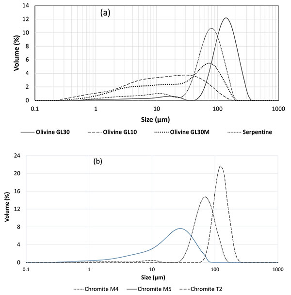
For development of the flotation method, M4 chromite grade was employed in a particle blend with regular GL30 olivine. As a matter of fact, this fraction has been selected because its size distribution centered at 70 µm (Fig. 2b), corresponds fairly well to the size of chromite particles contained in olivine, in the range 30-80 µm as shown by SEM observations (Fig. 3). M5 chromite is smaller than M4 grade with an average size around 35 µm, whereas coarser chromite T2 has an average size around 120 µm.
2.4.2. Physicochemical Analyses
The mineral composition obtained by XRD confirmed that the olivine used (Sibelco) consists mainly in forsterite and fayalite, which are magnesium and iron silicates, with the presence of other minerals, as shown in Table 1. Serpentine consists mainly of lizardite, a hydrated form of forsterite, in addition to forsterite and fayalite. From XRD measurements, it appears that the chromite particles to be separated from olivine include iron and magnesium oxides with a stoichiometry fairly close to that of “ideal” Cr2O3-FeO (Table 1). The stoichiometry differs from that in the additional M4 chromite by appreciable substitution of Fe and Cr by Mg and Al respectively, as shown in Table 1. Grades M5 and T2 are of comparable compositions.
| Minerals | Composition | Chemical Formula |
|---|---|---|
| Olivine | Forsterite, Fayalite Silicon oxide Magnesio-chromite Chrysotile |
(Mg1,636Fe0,364) (SiO4) SiO2 Cr2O3, Mg0,131Fe0,869O Mg3 (Si2-xO5) (OH)4-4x |
| Serpentine | Lizardite Forsterite, Fayalyte |
Mg3 (Si2O5) (OH)4 (Mg1,785Fe0,216) (SiO4) |
| Chromite M4, M5, T2 | Magnesium chromium iron aluminum oxide | Mg0,4Cr1,42Fe0,65 Al0,41 O4 |
Because of their same origin, the three olivine grades used exhibit very similar composition, so only the data for GL30 olivine have been given here. Nevertheless, the average composition given by EDX differs to some extent from XRD measurements on forsterite-fayalite particles, mainly by the higher Fe content revealed by XRD (Table 2). For comparison between the two techniques of characterization, the mineral composition obtained by DRX analysis which provides the number of moles for a particle was converted into the mass concentration of elements.
| Minerals | GL30 Olivine | Forsterite in Olivine | Serpentine | M4, M5, T2 Chromite | M4, M5, T2 Chromite | Chromite in GL30 | Chromite in GL30 |
|---|---|---|---|---|---|---|---|
| Element/ method |
EDX | XRD | EDX | EDX | XRD | EDX | XRD |
| O Mg Al Si Cr Fe Ni Others |
46.5 26.9 0.6 20.8 0.23 4.24 0.46 0.27 |
42.9 28.3 - 18.9 - 9.92 - - |
49.3 24.6 0.89 20.0 0.19 4.16 0.41 0.34 |
31.8 7.59 8.48 3.64 30.5 17.4 0.4 0.23 |
32.8 4.99 5.68 - 37.9 18.6 - - |
32.3 11.0 1.52 5.25 31.5 18.2 0.35 0.11 |
29.1 1.45 - - 47.3 22.1 - - |
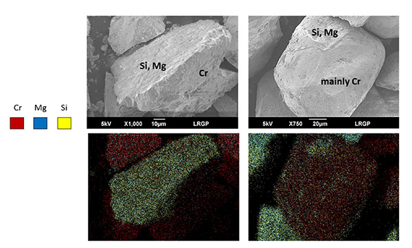
The chromite used (fractions M4, M5 and T2) contains Cr and Fe near 30.5 and 17.4 wt% respectively as revealed by EDX measurements on the overall surface of chromite particles with appreciable presence of magnesium (8.4 wt%) and silicon (5 wt%). EDX observations of isolated particles confirmed the above composition. The composition obtained by XRD slightly differs from that of chromite particles observed by EDX, with far larger Cr content (37.9 wt%), and lower amounts of Mg and Al elements, at 5 and 5.7 wt% only (Table 2): this composition would correspond to substituted chromite of approximate stoichiometry Cr1.5Al0.5O3 Fe0.6Mg0.4O. In spite of the observed difference in Cr content, both techniques showed the presence of Mg/Fe silicates in the commercial chromite. From SEM-EDX observations, both nearly pure chromite particles and mixed chromite-silicate particles are present in the mineral considered, as exemplified in Fig. (3) (left).
XRD observations of chromite particles contained in GL30 olivine led to local compositions very close to the ideal form of chromite Cr2O3-FeO, without aluminium detected and a very low magnesium concentration (Table 2): the two chromites considered here exhibit different stoichiometries. EDX measurements have been carried out with chromite-concentrated olivine fractions, that have been prepared, using a portable magnet and moving it through a shallow bed of olivine particles: the simple technique could yield a few grams of a solid blend with an overall chromite content larger than a few percentages which allowed EDX measurements on various chromite particles. On average, appreciable contents of magnesium and silicon were observed in the chromite particles observed from this blend (Table 2): this means that chromite in GL30 olivine exists also in the form of mixed chromite-silicate particles as shown in Fig. (3), right.
3. DEVELOPMENT OF THE FLOTATION METHOD
For flotation tests, 500 mL liquid solution then 15 g particles were introduced in the column and runs were operated batchwise. The froth containing recoverable particles was mechanically collected from the overflowing matter in separate vessels for one hour. Then, the collected particles were washed with deionized water, filtered and allowed to dry before their characterization. Besides, to compensate the regular entrainment of the liquid in the froth, solution has been continuously introduced along the flotation run, into the column bottom at 3.5 cm3/min using a syringe pump which allowed steady froth depth.
The flotation method has been developed after addition of 3.3 wt% M4 chromite to GL 30 olivine particles to magnify the possible separation of the two minerals by flotation. Because of the presence of chromite in GL30 olivine, the initial content of chromite in the input solid was near 3.7 wt%. The development has been made in terms of electrolyte solution and hydrodynamic conditions. In most cases, replicate experiments and analysis of the solid particles recovered have been carried out to check the repeatability of the runs made, and to validate the protocol defined.
3.1. Suitable Gas Flow Rate and Hydrodynamic Observations Without Stirring
Preliminary tests have been carried out without stirring to determine the flow rate of injected gas. The solution was a dilute NaOH solution at pH 11, with 150 mg/L CTMAB [22]. Other collectors reported in the literature e.g. sodium oleate or dodecylsulfonate at pH 4 but the poor performances obtained led us to use exclusively CTMAB.
For experiments, 450 mL solution have been introduced first into the column; then the particles were introduced and the column wall was rinsed by pouring the remaining 50 mL. To avoid too rapid settling of the particles, gas had to be introduced at the pre-defined rate within a few seconds, initiating then the flotation run. With CTMAB, froth formation and possible flotation could not occur in a satisfactory manner for flow rates below 80 Ncm3/min, corresponding to superficial gas velocity, uG, at 0.11 cm/s. In the range 100 – 250 Ncm3/min, in spite of different flow rates of particles collected in the froth, comparable extraction rate of chromite from the olivine stock was observed (data not shown). The reference flow rate of nitrogen injected was fixed at 150 Ncm3/min for the results presented below. For such conditions, the height of the froth was of 18 ± 2 cm. In most papers published in columns [18, 19, 21, 23], or in other flotation devices [17, 24, 25], the superficial gas velocity was in the range 1-2 cm/s. However, in other papers gas velocity in the order of 0.2 cm/s was also employed [4, 21, 22]. The gas holdup in the column, εG, has been estimated to approx. 2% from the variation of the upper liquid level in the column after sudden interruption of the gas feed: this value is slightly lower than values in the range 3-8% which can be deduced from formerly published investigations [5, 17-19, 25]. The actual average velocity of gas bubbles, ub, defined as the ratio (uG/εG) was near 10 cm/s, in accordance with visual observation of the gas bubbles in the Perspex column, in the range 6-10 cm/s. This real velocity corresponds to residence time of the gas in the liquid column in the range 4-7 s, in fair consistence with the residence times that can be estimated from the data reported in [18-24] and ranging from 5 to 20 s.
3.2. Selection of the Optimal Electrolyte Solution
Prior to experiments in the column, zeta potential of the particles has been measured depending on the solution pH and collector concentration. First, the pH of a 150 mg/L (0.41 mM) CTMAB solution was adjusted before analyses, using 0.1 M solutions of sodium hydrogen phthalate and sodium hydrogen carbonate for pH 4 and 8, or aliquots of 1 M sodium hydroxide added to deionized water for pH 11. With a zeta potential of -30 mV in a 1 mM NaCl solution the surface of chromite particles with CTMAB can attain its point of zero charge (pzc) for pH near 4 (Fig. 4a). However, the surface charge of olivine particles was found comparable to that of chromite particles for pH 4 and 8 which is to affect the flotation selectivity. In contrast, different values of zeta potential of the two mineral surfaces could be obtained for pH 11.
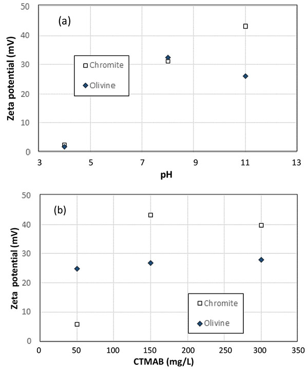
Conferring to this observation, the influence of CTMAB concentration is shown in Fig. (4b) for a pH fixed at 11. According to the data obtained, the optimal conditions for flotation could be found with a CTMAB concentration of 50 mg/L (0.14 mM), for which the zeta potential of chromite and olivine particles is respectively at 5.5 and 24.5 mV, whereas it attains respectively 42 and 25 mV with CTMAB concentration at 150 mg/L or higher (Fig. 4b).
Flotation tests have been made with 50 and 150 mg/L CTMAB at pH 11, with the flow conditions developed (section 3.1). With 50 mg/L CTMAB, the dispersion of gas bubbles was shown to be less efficient, and the froth quality was not sufficient to collect particles by overflow after 15 minutes, forcing the run to be stopped, with chromite recovery near 40% (15% of the solid recovered in the froth). Replicate runs confirmed the trend after comparable periods of time. The discrepancy between the flotation tests and zeta potential measurements, both with 50 mg/L, can be explained by the fact that CTMAB is acting as both frother and collector in the process. Contrary to what happens in the very diluted suspensions in zetameter cells, part of the collector added is adsorbed on the column wall and mainly on the gas bubbles (as frother): therefore, the theoretical concentration at 50 mg/L is far from sufficient for long period flotation, in addition conducted with appreciable fractions of suspended solids. In contrast, use of 150 mg/L CTMAB allowed to recover in the froth nearly 90% of the particles introduced as shown in Fig. (5a).
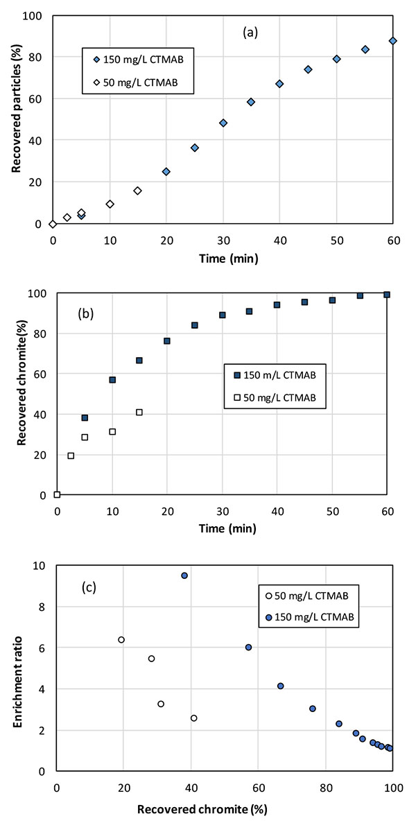
The amount of chromite extracted by flotation was also affected by the amount of introduced CTMAB (Fig. 5b). The enrichment ratio at time t was defined as the chromite concentration in the solid recovered from initial time to t (called chromite recovery) over the chromite content in the input solid blend. This ratio actually expresses the selectivity of the flotation process. The chromite recovery progresses along time but the enrichment ratio was observed to decrease with the fraction of recovered chromite in the discontinuous runs, without addition of fresh particle blend (Fig. 5c). With the higher CTMAB fraction, the first 5% solid recovered in the froth within the 5 first minutes, contained approx. 8 times more chromite that the initially introduced mineral blend, with a chromite recovery near 40% (Fig. 5c). With the lower CTMAB concentration, the enrichment ratio decreased from 6 to 2.3 after 15 minutes, for 40% chromite recovery. In the following sections, the flotation liquid was a NaOH solution at pH 11 with 150 mg/L CTMAB.
3.3. Effect of Stirring in Flotation Efficiency
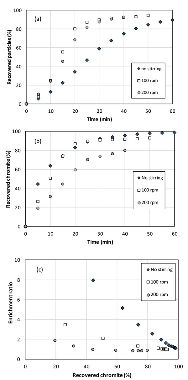
Test have been conducted with the agitation system (Fig. 1b) at 100 rpm and 200 rpm with the same gas flow rate to enhance the bubble-particle collision and the collector diffusion to the particle surface. It has been found that stirring in the column bottom led to faster recovery of solid particles in the froth than with the only injection of nitrogen, as shown in Fig. (6a). After 20 min around 75% particles could be collected with stirring at 100 and 200 rpm, whereas the corresponding particle recovery was less than 40% within this time lapse. Recovery of chromite particles was also observed to largely depend on agitation conditions: more intense agitation appears detrimental to chromite recovery (Fig. 6b): after 20 minutes, 80% of the chromite particles have been extracted from the initial blend at 100 rpm or without agitation, whereas the fraction was only near 60% at 200 rpm. All in all, the enrichment ratio was observed to be reduced by increased agitation rate. For tests without agitation, the enrichment ratio of chromite attained 8 for chromite recovery near 40%, with 5% collected particles, and 3.5 in the solids collected for 75% chromite recovery (Fig. 6c). This performance is far better than with agitation: the enrichment ratio at 40% chromite recovery attained only 2.2 and 1.3 at 100 and 200 rpm respectively, whereas it laid close to unity for chromite recovery larger than 60% at 200 rpm.
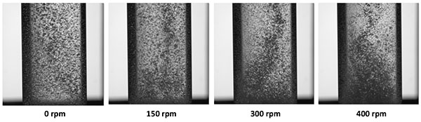
Stirring initially thought to improve bubble-particle interactions, was actually shown here to induce the transport of particles to the column wall with the inhomogeneous dispersion of the gas bubbles which affects the flotation efficiency. In order to highlight this point, different conditions of agitation have been compared to observe flow phenomena in the flotation column without or with stirring from 100 to 400 rpm (Fig. 7). For possible visualization, mineral particles were not introduced in the photographs presented in Fig. (7). Without stirring, the gas bubbles appear evenly distributed in the column. Stirring the G/L medium was shown to be detrimental to quality and homogeneity of the gas dispersion in the solution, with the formation of a central vortex at high rotation speed. Mechanical agitation in the small column, with segregation of gas phase – in the central vortex - from the solid phase centrifuged to the column wall, actually impedes the flotation process.
This observation which may appear different from what is usually reported [5, 12, 13, 25], is due to the small diameter of the column and the short distance (near 12 mm) between the impeller and the sintered plate (Fig. 1b). In the present investigation, further experiments have been conducted without stirring.
3.4. Effect of Particle Size
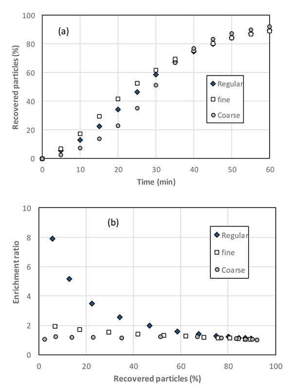
Because flotation is based on the upward transport of the particles by the action of bubbles, the particles size is to influence the separation efficiency because of gravity: as a matter of fact, both surface phenomena and aptitude to settling are to be involved in the overall flotation process. Tests have been conducted using the “regular combination” (GL30 olivine – M4 chromite), then the ‘fine blend’ formed with GL10 olivine and M5 chromite particles, and the ‘coarse blend’ prepared with GL30 olivine and T2 chromite particles Fig. (8). In all cases, chromite particles were added to olivine at 3 wt.% of the overall input fraction.
Flotation of the coarsest particles was found to be slightly more troublesome than with smaller particles (data not shown): as a matter of fact, flotation is known to be little suitable for particles larger than 100 µm or below [12, 13, 23]. Analysis of the floated particles revealed than the chromite recovery from the “fine” and the “coarse” blends is less effective than from the regular (GL30 olivine-M4 chromite) blend (Fig. 8a). As a consequence, the enrichment ratio is dramatically poor with the fine and the coarse particle blends (Fig. 8b) with ratio values below 2 even in the first minutes of the run, for which the selectivity is supposed to be maximal.
Attempts in interpretation are presented below. Flotation is actually to be hindered by occurrence of particle settling, whose significance is governed by adhesion of/to gas bubbles, drag forces and the intrinsic settling aptitude of these particles, as expressed in previous works [18, 23, 26].
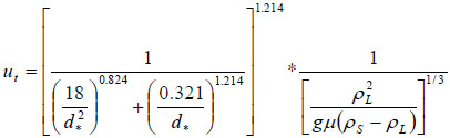
In a first approach, the settling aptitude has been quantified here from the terminal falling velocity, assuming monodisperse, spherical particles and neglecting solid-solid particles in the media. Also neglected in the simple approach is the presence of the injected gas, whose motion is to affect the dynamics of the particles. For this purpose, the terminal velocity ut has been calculated for the various particles using the correlation suggested by Turton and Clark [27]:
 |
(1) |
with
 |
(2) |
where d is the average particle diameter, g is the acceleration due to gravity, ρL, the density of the liquid phase, ρS, the density of the suspended materials (approx. 3300 kg/m3 for olivine, 4100 kg/m3 for chromite), and μ the viscosity of the solution, taken at 10-3 Pa.s. The terminal falling velocities of GL30 and M4 minerals were estimated respectively at 0.0172 and 0.0080 m/s (Table 3).
| Olivine GL10/ GL30M |
Olivine GL30 |
Chromite M5 |
Chromite M4 |
Chromite T2 |
|
|---|---|---|---|---|---|
| Mean diameter (µm) | 20 | 120 | 30 | 70 | 120 |
| Terminal falling velocity (m/s) |
4.9 10-4 | 0.0172 | 0.0015 | 0.0080 | 0.0232 |
For such conditions, separation is favored by both the selectivity in particle adhesion to gas bubbles and the settling aptitude. For the two other mixtures of fine and coarse particles, the terminal falling velocity of chromite particles is higher than that of the considered olivine fractions: in such cases the gravity phenomenon opposes surface phenomena, leading to very poor flotation efficiency. For the fine particles, the enrichment ratio attained only 2 for a chromite recovery at 15%, far below that with the reference blend. The flotation of coarse particles (GL30 olivine -T2 chromite) appears really difficult because of the high value for ut, larger than 0.02 m/s, somewhat larger than that of GL30 particles. For this last blend, it is likely that the chromite particles over 100 µm are too large for efficient flotation.
4. SEPARATION OF CHROMITE FROM VARIOUS CHROMITE-OLIVINE BLENDS
4.1. Varying the Chromite Content in the Solid Blend to be Treated
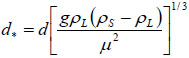
From the experience gained, further flotation tests have been conducted by treating 15g solids with higher contents of Sibelco chromite in the column to emulate a multistage flotation process with the same fraction of solids, to maintain constant the solid residence time in the column and the multiphase flow conditions. Regular (GL30 olivine -M4 chromite) combination has been considered here. The recovery of solids by the froth along the discontinuous run was little affected by the initial chromite content (data not shown), however the fraction of recovered chromite appeared very dependent on the input composition (Fig. 9a). With exception of data obtained with 3 and 5% chromite, the more concentrated the blend, the faster the recovery of chromite particles: in particular, for the 20% chromite blend, more than 93% of the introduced chromite could be extracted within 10 minutes, to be compared with the 63% chromite recovery obtained in this time lapse when using the 3.3% chromite enriched olivine. As expected, the enrichment ratio calculated is a decreasing function of the separation progress in the discontinuous tests. No real correlation could be found between the enrichment ratio and the fraction of recovered chromite (data not shown), but as shown in Fig. (9b), the experimental values for the enrichment factor E could be well correlated when plotted versus the particle recovery fraction R, and for the operating conditions considered, the following numerical law has been found:
 |
(3) |
where R is expressed in percentages, a=86.7%, b=6.3% and c=0.26. Coefficients a, b, and c of the above relation have a restricted physical meaning since they depend on the system used (column, electrolyte) and the flow conditions. Nevertheless, rel. (3) expresses that the enrichment ratio does not depend on the chromite content of the solid to be treated.
4.2. Extraction of Chromite from Original Minerals
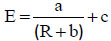
The operating protocol developed above has been applied to the treatment of the original minerals. Flotation tests have been conducted on the various olivines (GL30, GL30 Milled and GL10) to confirm the suitable particles size distribution, and with serpentine.
Best performance of chromite particles from the mineral has been obtained using olivine GL30: chromite recovery attained 90% after one hour (Fig. 10a) and the enrichment ratio peaked at 3 in the first minutes, however with a regular decreasing trend along the run (Fig. 10b). Flotation using G30 Milled olivine and serpentine allows enrichment ratio of 1.25 to 1.5 only in the first half of the flotation test. Chromite separation from GL10 olivine, which is the finest mineral was observed to be of nil efficiency. Because a significant fraction of particles is below 20 µm in olivine GL10 and GL30 Milled, mineral particles can be entrained with little effect of zeta potential in gas-solid interactions, resulting in a very poor selectivity: the reduction in gas flow rate should improve the separation efficiency, but other separation techniques would also be considered. For serpentine, which is a hydrated form of iron and magnesium silicate, the density of 2.5-3.0 g/cm3 - somewhat below than olivine - may also affect the flotation selectivity with the same consequence as for fine particles. Moreover, due to the presence of hydroxide groups on the silicon atoms, serpentine exhibits likely different affinity to the collector from that of olivine, resulting in less efficient adsorption on this mineral.
Considering the initial target, flotation of chromite particle as a pretreatment of the olivine feedstock is more selective with GL30 olivine. However, the modest efficiency of chromite separation is partly due to very poor chromite content (near 0.5 wt%) in the olivine studied. Moreover, chromite is also present in mixed chromite-olivine solid particles, as shown in Fig. (3), in addition to pure chromite particles: the behavior of these mixed particles in the flotation column is to be intermediate between those of pure chromite and pure olivine particles, rendering their separation from chromite-free olivine more difficult.
CONCLUSION
Considering the initial project of the olivine carbonation reaction, flotation of chromite particles as a pretreatment of the feedstock is more selective with olivine GL30 which corresponds to the actual mineral considered for CO2 sequestration. Operating conditions for the laboratory flotation column have been optimized. The mean particles size of olivine fraction enhances the chromite flotation because of the additional contribution of gravity in the separation process. In addition, the use of 120 µm GL30 olivine avoids additional energy and costs of grinding in comparison to finer GL10 and GL30 Milled fractions. After the promising results obtained with 3.3 – 20% chromite-enriched olivine fractions, the method has been applied to the minerals to be used in CO2 sequestration. In all cases, extraction of chromite from low-chromite containing olivine is difficult, with modest enrichment ratios, even with GL30. The existence of mixed particles in the minerals fractions used has to be better characterized with respect to their behavior in flotation process for possible improvement of the flotation process. Pre-treatment of the olivine stock may also be considered.
ETHICS APPROVAL AND CONSENT TO PARTICIPATE
Not applicable.
HUMAN AND ANIMAL RIGHTS
No Animals/Humans were used for studies that are base of this research.
CONSENT FOR PUBLICATION
Not applicable.
CONFLICT OF INTEREST
The author (editor) declares no conflict of interest, financial or otherwise.
ACKNOWLEDGEMENTS
This work has been carried out with the Valorco project (Valorisation of CO2) with ArcelorMittal and fully funded by ADEME. Thanks are also due to Philippe Arnoux and Thibault Roques-Carmes (LRGP) for measurements of zeta potentials and fruitful discussions, and to S. Diliberto (IJL) for valuable XRD analysis of minerals.