All published articles of this journal are available on ScienceDirect.

Optimization and Application of Reciprocating Direct-Drive Electric Submersible Plunger Pump Lifting System in the Xinjiang Oilfield
Authors Info & Affiliations
Abstract
Background:
A reciprocating direct-drive electric submersible plunger pump (RDD-ESPP) lifting system is an innovative rodless lifting method, which uses a downhole linear motor to directly drive the plunger pump to lift the fluid. This method effectively overcomes the problems encountered in a conventional sucker rod pumping system, such as severe eccentric wear between the sucker rod and the tubing, higher energy consumption and frequent pump maintenance.
Objective:
In this manuscript, the objective is to propose a methodology on optimizing the working parameters of RDD-ESPP lifting system and validate the theory with field case.
Methods and Results:
Mathematical models for the wellbore temperature distribution, lifting load, pump efficiency, system efficiency and tubing strength validation are established. A selection process for the optimal working parameters is proposed, and a parameter sensitivity analysis is implemented. The results show that pump efficiency is largely affected by gas and leakage, and there are reasonable pump submergence depths in oil wells for different produced gas-to-oil ratios. A field application test in a low-production well resulted in a 33.5% power savings rate and 41.6% improvement in the pump efficiency.
Conclusion:
RDD-ESPP lifting system has a promosing potential on power savings and consumption reduction compared with conventional sucker rod pumping system.
1. INTRODUCTION
With increasing demands on energy consumption, more low-permeability oil reservoirs are being exploited and developed in China. Usually, the drilled wells in such low-permeability oil reservoirs have a lower productivity, a deeper liquid level, and some even have some curved sections. These factors restrict the pump depth of a conventional sucker rod pumping system and result in a series of problems, such as an increasing pumping unit load, a deteriorating sucker rod stress condition, and increasing eccentric wear between the rod and tubing. To meet the production requirements of low-production, low-pressure reservoirs and deeper wells, many measures and new equipment are being developed and applied in oilfields. A Reciprocating Direct-Drive Electric Submersible Plunger Pump (RDD-ESPP) is a new linear fting system technology and is popularly used in Chinese oilfields because of its unique characteristics, such as eliminating eccentric wear between the rod and tubing and permitting more advanced automation, variable frequency adjustments, simpler surface facilities, lower maintenance costs, higher efficiencies and its suitability for use in low-production wells [1].
The RDD-ESPP is an innovative rodless pumping method. A linear motor deployed downhole drives the plunger pump up and down, which lifts the formation fluid to the surface. In this way, the intermediate mechanical transmission mechanisms, such as the surface pumping unit and sucker rod, are eliminated. Such a design contributes to improving the lifting efficiency and decreasing the pump energy consumption. In the Daqing oilfield, RDD-ESPPs have been used in 108 oil wells (including 54 vertical wells, 47 deviated wells and 7 horizontal wells). The average pump efficiency is 67.06%, and the average daily power consumption is 57.5 kWh. Compared with a conventional sucker rod pumping system operating at the same production rate, the electricity savings was 45.64% [2-5]. In the Changqing oilfield, a total of 27 oil wells in the low-permeability reservoirs of the Ansai and Longdong areas have adopted this new pumping method since its introduction in 2007. The average pump efficiency increased from 41% to 65%, and the energy savings rate was 22%. The maximum operating period was as much as 813 days [6-8]. In 2011, an RDD-ESPP was used in 5 deviated oil wells in the Zhengting oilfield. These wells have substantial eccentric wear between the rod and tubing, frequent workover and lower production rates when using sucker rod pumping systems. With this RDD-ESPP, the pump efficiency improves by 60.6%, the daily power consumption decreases by 39.9 kWh, and the pump maintenance period is prolonged to 46 days [9]. The Jinlin oilfield has also installed RDD-ESPPs in 11 oil wells by the end of 2014. Here, the average pump and average system efficiencies improved from 25.3% to 79.6% and 9.37% to 16.67%, respectively. The pump maintenance period was extended from 303 days to 503 days and the daily power consumption decreased from 112.7 kWh to 77.6 kWh [10].
The successful application of an RDD-ESPP results in energy savings, improved pump efficiency and significant decreases in the operating costs. However, the operating parameters (such as pump depth, pumping speed and power frequency) of RDD-ESPP lifting systems are mainly determined or adjusted according to the maximum linear motor thrust force and/or by monitoring the operating state in the field. At present, there is no systematic method to guide the design and evaluation of such a system. The primary focus of our study is to develop a theoretical method to determine the optimal working parameters for an RDD-ESPP lifting system and provide a decision process for field operations. Firstly, mathematical models for calculating the wellbore temperature distribution, lifting load, pump efficiency and system efficiency are developed based on the working principle of the RDD-ESPP and its rodless system configuration. Then, the effects of the pump depth, pump diameter and pumping speed on the lifting efficiency are studied. Finally, the working parameter for low-production and deep wells in the Xinjiang oilfield are optimized and applied. This study provides a theoretical method for selecting the optimal operating parameters for RDD-ESPP lifting systems and analyzes its working state. In this way, we avoid making design decisions by relying solely on field experience.
2. RECIPROCATING DIRECT-DRIVE ELECTRIC SUBMERSIBLE PLUNGER PUMP LIFTING SYSTEM
2.1. System Components and Characteristics
The RDD-ESPP lifting system consists of a downhole linear motor, an electrical submersible plunger pump, a surface control unit, and a power transmission cable, as shown in Fig. (1). The frequency of the alternating current is firstly adjusted by the surface control unit. Then, current is transferred to the downhole linear motor. The downhole linear motor makes a reciprocating movement due to the effect of electromagnetic induction, which drives the plunger directly connected to the mover, moving it up and down. Then, the formation fluid is continuously lifted to the surface after being pressurized by the pump [11, 12].
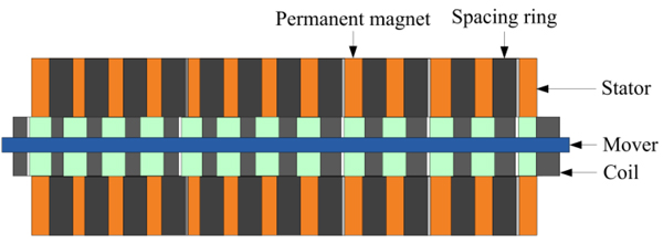
2.1.1. Downhole Linear Motor
The downhole linear motor is made up of a stator, mover and coil, as shown in Fig. (2). When an alternating current passes through the stator, a travelling magnetic field is generated. When the field interacts with the permanent magnet fixed on the mover, a linear thrust force is produced. The reciprocating movement of the mover is realized by changing the phase sequence of the power supply.
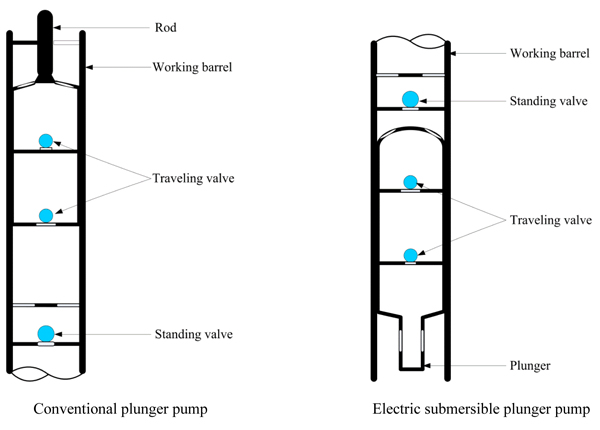
2.1.2. Electrical Submersible Plunger Pump
Different from a conventional plunger pump used in a sucker rod pumping system, the standing valve for the electrical submersible plunger pump is placed on the upper section of the working barrel, while two travelling valves are separately placed both above and below the plunger and are located on the bottom section of the working barrel (Fig. 3). The plunger is directly connected to the mover of the downhole linear motor through a push rod. During the upstroke, the mover of the downhole linear motor drives the plunger upward, the travelling valve closes and the pressure in the working barrel increases. When the pressure in the working barrel is larger than the static pressure of the liquid column in the tubing above the pump, the standing valve opens. Then, the fluid in the working barrel discharges into the tubing. During the downstroke, the plunger moves downward under the reverse movement of the mover. The pressure in the working barrel decreases, and the standing valve closes. When the pressure in the working barrel is lower than the pump inlet pressure, the traveling valve opens and the formation fluid enters the working barrel. Under the effects of this cycling process, the formation fluid is lifted continuously to the surface.
2.1.3. Surface Control Unit
Controlling the operating state of the downhole linear motor is the key technology that must be mastered for the smooth operation of the reciprocating movement of an electric submersible plunger pump. Such operation is realized by surface variable-frequency control technology. The three-phase alternating current is firstly rectified into single-phase direct current, which is then inverted into square-wave alternating current at the required frequency. The intelligent control technology and high-performance electronic components are integrated to realize different control functions, such as constant-speed stepping, intermittent power supply, repeated startup and shutdown operations, repeated direction changes, automatic restart after power cut-off, automatic alarm and protection.

2.1.4. Advantage and Disadvantage
Compared with conventional sucker rod pumping systems, the RDD-ESPP lifting system has several obvious advantages. Firstly, the problem of eccentric wear between the rod and tubing, which results in rod parting and tubing leakage, is completely eliminated with this technology. This can greatly prolong pump maintenance periods and reduce operating costs. The pump is very suitable for vertical, directional and horizontal wells characterized by low-production rates and low-permeability. Secondly, there are no speed-reducing and reversing mechanisms; power is supplied intermittently, resulting in promising energy savings. Thirdly, the plunger works constantly, meaning there are no stroke losses. Therefore, higher pumping efficiency is expected. Finally, surface operations and facility maintenance become easier. The working parameter settings (such as stroke, speed and power frequency) can be easily implemented via the surface control unit. This largely alleviates labor requirements for field engineers. However, there are still some production problems that need to be solved, such as dealing with paraffin deposits. With conventional sucker rod pumping technology, the reciprocating movements of the sucker rod string contributes to scraping and removing the deposited paraffin. However, the RDD-ESPP lifting system does not have a moving rod string and the deposited paraffin on the tubing wall is not removed over time. Therefore, measures are needed to prevent and remove paraffin deposits when utilizing this technology.
2.2. Recommended Practice
At present, the stroke of the downhole linear motor is usually fixed at 1.23 m and the pumping speed can be adjusted from 0.1 rpm to 8 rpm. Due to the special design of the downhole linear motor, the maximum pump depth and displacement are limited. The recommended practices as defined by the manufacturer are listed in Table 1.
3. METHODS
3.1. Mathematical Model
When compared to conventional sucker rod pumping systems and electrical submersible pumping systems, there are some significant differences in the RDD-ESPP lifting system. Therefore, the mathematical models for the lifting design are also different. 1) Compared with conventional sucker rod pumping systems, the RDD-ESPP lifting system does not need a rod string to transfer power. Therefore, the lifting load model and pump efficiency model do not need to consider the effects of rod weight and its elastic stretching and shrinking. 2) Compared with conventional electrical submersible pumping systems, the temperature model only needs to consider the ther mal effects of the motor and cable. 3) The RDD-ESPP pumping system works using an intermittent power supply, meaning that the input power depends on the power supplied during the time required for the upstroke and downstroke.
| Linear Motor | Rated Voltage /V |
Rated Power /kW |
Maximum Motor Thrust Force /kN |
Pump Diameter /mm |
Maximum Displacement /(m3/d) |
Maximum Pump Depth /m |
|---|---|---|---|---|---|---|
| WFQYDB-114-380-(8~15) | 380 | 15 | 8 | 28 | 7 | 1000 |
| 32 | 10 | 800 | ||||
| WFQYDB-114-380-(10~20) | 380 | 20 | 12 | 28 | 7 | 1500 |
| 32 | 10 | 1100 | ||||
| WFQYDB-114-660-(20~35) | 660 | 35 | 24 | 28 | 7 | 2600 |
| 32 | 10 | 2200 | ||||
| 38 | 15 | 1500 | ||||
| 44 | 20 | 1000 | ||||
| 50 | 26 | 900 | ||||
| 57 | 35 | 800 | ||||
| WFQYDB-114-1140-(30~50) | 1140 | 50 | 45 | 32 | 10 | 3000 |
| 38 | 15 | 2500 | ||||
| 44 | 20 | 1600 | ||||
| 50 | 26 | 1400 | ||||
| 57 | 35 | 1200 | ||||
| 70 | 50 | 800 | ||||
| WFQYDB-114-1140-(40~80) | 1140 | 80 | 65 | 57 | 35 | 1600 |
| 70 | 50 | 1200 | ||||
| 83 | 75 | 900 | ||||
| 95 | 100 | 700 |
3.2. Mathematical Model for Wellbore Temperature
To acquire the temperature distribution in the wellbore, the following assumptions are made. 1) Radial heat losses between the wellbore and the formation are considered and axial heat losses along the wellbore are not included. 2) A steady-state heat transfer system is in existence in the downhole environment. 3) Heat capacity changes in the flowing fluid along the wellbore are very small and this value is taken as a constant. 4) The heat generated by the motor and cable are entirely contribute to heating the fluid. 5) The production rate is assumed to be constant.
According to the configuration of the RDD-ESPP lifting system, the wellbore temperature distributions are divided into three parts, namely, from the bottomhole to the motor, the motor and pump body, and from the pump outlet to the wellhead [13, 14].
3.2.1. Bottomhole-to-Motor Section
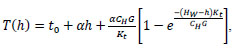
Using the energy balance equation, the fluid temperature in the bottomhole-to-motor section can be calculated using Eqn. (1):
 |
(1) |
where, T(h) is the temperature at any location in the bottomhole-to-motor section, °C; t 0 is the surface temperature, °C; α is the geothermal gradient, °C/m; Hw is the reservoir depth, m; h is the depth at any location in the bottomhole-to-motor section, m; Kt is the heat transfer coefficient between the fluid and the formation in the bottomhole-to-motor section, W/(m2·°C); CH is the fluid heat capacity, J/(kg·°C); and G is the fluid mass flow rate, kg/s.
3.2.2. Motor and Pump Body (Pump Outlet)
The pump outlet temperature is a comprehensive result of motor heating, cable heat dissipation, and heat exchange between the fluid and the formation. It can be calculated using Eqn. (2):
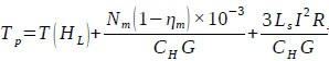 |
(2) |
Where Tp is the fluid temperature at the pump outlet depth, °C; T(HL) is the fluid temperature resulting from heat exchange between the fluid and the formation at the pump outlet depth and can be calculated by Eqn. (1), °C; HL is the pump outlet depth, m; Nm is the downhole linear motor input power, kW; ηm is the downhole linear motor efficiency, %; Ls is the length of the flat cable attached on the outside of the downhole linear motor, m; I is the working current of the downhole linear motor, A; and R is the resistance per unit length of the flat cable attached on the outside of the downhole linear motor, Ω/m.
3.2.3. Pump Outlet-to-Wellhead Section
In this section, the heat transfer includes the heat exchanged between the fluid and the formation, and cable heat dissipation. Similarly, the wellbore temperature at any point can be calculated via the energy balance equation, as expressed in Eqn. (3) and Eqn. (4):
 |
(3) |
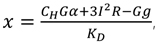 |
(4) |
where T(hD) is the temperature at any location in the pump outlet-to-wellhead section, °C; hD is the depth at any location in the pump outlet-to-wellhead section, m; KD is the heat transfer coefficient between the fluid and the formation in the pump outlet-to-wellhead section, W/(m2·°C); and g is gravitational acceleration, which is defined as 9.81 m/s2.
3.3. Mathematical Model for Lifting Load
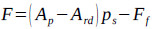
According to the working principle of the RDD-ESPP, the standing valve opens and the traveling valve closes during the upstroke. At this condition, the liquid column in the tubing above the pump acts on the plunger. Considering the inertial effect of the liquid column and the friction between the plunger and the working barrel, the load acting on the downhole linear motor can be calculated using Eqn. (5) [15, 16]:
 |
(5) |
Where F is the load acting on the downhole linear motor, N; Ap is the cross sectional area of the plunger, m2; Ard is the cross sectional area of the push rod connecting the downhole linear motor and the plunger, m2; pd is the pressure at the pump outlet depth or the discharge pressure, pa; ps is the pressure at the pump inlet depth or the submergence pressure, pa; Ff is the friction force between the plunger and the working barrel, N; and Finertia is the inertial force of the liquid column, N.
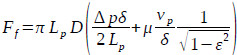
The friction force between the plunger and the working barrel can be calculated using Eqn. (6):
 |
(6) |
Where Lp is the plunger length, m; D is the plunger diameter, m; Δp is the pressure difference across the pump plunger, Pa; δ is the radial clearance between the pump plunger and the working barrel, m; μ is the fluid viscosity, Pa.s; vp is the plunger moving velocity, m/s; ε is the eccentricity ratio, which is defined as ε = e/δ and is dimensionless; and e is the eccentricity between the pump plunger and the pump inner diameter in m.
The inertial force of the liquid column is calculated by an empirical equation as follows:
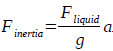 |
(7) |
Where a is the acceleration of the pump plunger, m/s2, and Fliquid is the static load of the liquid column, kN.
During the downstroke, the standing valve closes and traveling valve opens. This causes the submergence pressure to act on the pump plunger and the liquid column to act on the tubing. At this time, the load exerted on the downhole linear motor is calculated using Eqn. (8):
 |
(8) |
3.4. Mathematical Model for Pump Efficiency
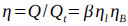
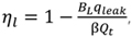
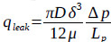
The plunger is directly driven by the downhole linear motor. The pump efficiency for the RDD-ESPP lifting system is mainly affected by the gas volume in the pump, the pump leakage rate and the volume change of the liquid in the pump. Therefore, the pump efficiency for the RDD-ESPP lifting system is defined as follows:
 |
(9) |
 |
(10) |
 |
(11) |
 |
(12) |
 |
(13) |
 |
(14) |
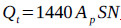 |
(15) |
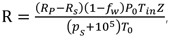
Where η is the pump efficiency, dimensionless; β is the pump admission coefficient, dimensionless; ηl is the pump leakage coefficient, dimensionless; ηB is the liquid volume effect coefficient, dimensionless; Q is the real production rate, m3/d; Qt is the theoretical production rate, m3/d; BL is the liquid volume coefficient, dimensionless; qleak is the pump leakage, m3/d; fp is the cross sectional area of the plunger; m2; S is the stroke, m; N is the pumping speed, rpm; K is the pump clearance ratio, dimensionless; R is the gas-to-liquid ratio in the pump, m3/m3; RP is the produced gas-to-oil ratio at the surface, m3/m3; RS is the dissolved gas-to-oil ratio in the pump, m3/m3; fw is the water cut, dimensionless; P0 is the absolute pressure at standard conditions and is defined as 105Pa; T0 is the absolute temperature at standard conditions and is defined as 293K; Tin is the absolute temperature at the pump inlet; and Z is the gas compression factor, dimensionless.
3.5. Mathematical Model for System Efficiency
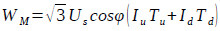
Due to no speed-reducing and reversing mechanisms and by adopting an intermittent power supply, the RDD-ESPP lifting system will save more energy than a conventional sucker rod pumping system. When the working frequencies for the upstroke and downstroke are known, the daily power supply time can be calculated with the pumping speed. Then, the daily power consumption can be calculated using Eqn. (16) [17]:
 |
(16) |
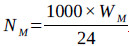 |
(17) |
Where WM is the daily power consumption, kWhUS is the surface voltage, V; IU is the upstroke current, A; Id is the downstroke current, A; Tu is the daily running time of the upstroke, h; Td is the daily running time of the downstroke, h; cosφ is the power factor, dimensionless; and NM is the surface input power, W.
Then, the system efficiency of an RDD-ESPP lifting system can be defined by Eqn. (18):
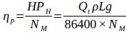 |
(18) |
Where ηp is the system efficiency, dimensionless; HPH is the hydraulic power, W; Qt is the daily production rate, defined as t/d; ρ is the liquid density, kg/m3; and L is the effective lifting head, m.
3.6. Mathematical Model for Tubing Safety Validation
When the RDD-ESPP lifting system is in operation, the maximum tubing tensile force appears at the wellhead. To ensure operational reliability and safety, the tubing strength should be evaluated. The weights of the tubing string, liquid column in the tubing, cable, pump and motor and vibration load are included in the tubing safety validation:
 |
(19) |
 |
(20) |
Where Ft is the total load acting on the wellhead tubing hanger, t; Wtube is the tubing string weight, t; Wliquid is the liquid column weight, t; Wcable is the downhole cable weight, t; Wpump is the pump weight, t; Wmotor is the motor weight t; Wvib is the vibration load, t; σt is the tensile strength of the tubing thread buckle, t; and [S] is the safety coefficient, dimensionless.
Usually, it is very difficult to calculate the vibration load, which is affected by the motor’s vibration frequency, the tubing string’s natural frequency, the liquid damping coefficient and other factors. During lifting design, one way to tackle this problem is to use a larger safety coefficient to ensure proper tubing strength.
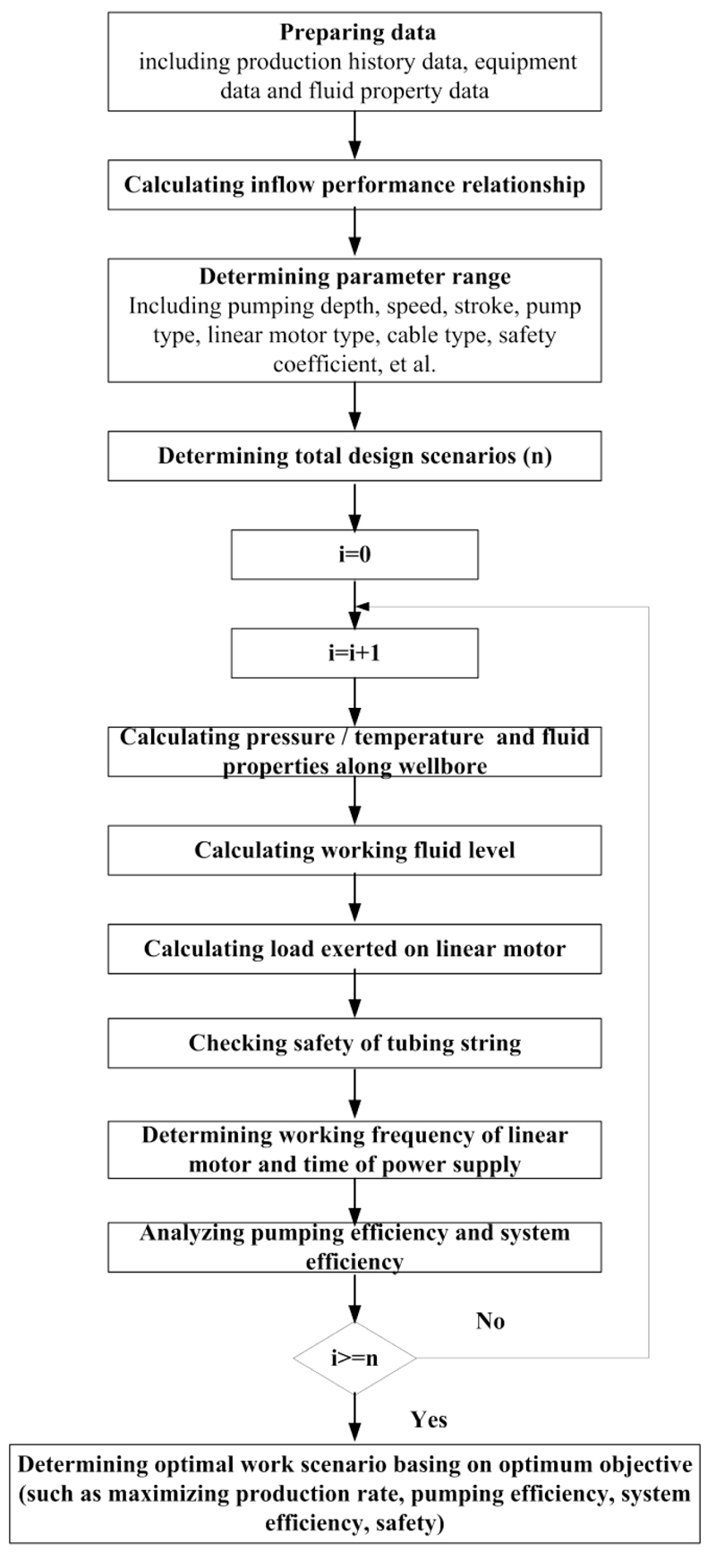
3.7. Lifting Design Process
The Beggs-Brill method is used to calculate the pressure distribution in the wellbore. Based on the aforementioned developed mathematical models, nodal analysis method is adopted to select the optimal working parameters for an RDD-ESPP lifting system. Fig. (4) shows the detailed calculation and optimal working parameter selection processes.
4. RESULT AND DISCUSSION
4.1. Sensitivity Analysis and Case Study
4.1.1. Parameter Sensitivity Analysis
From the developed mathematical models, we see that the pump efficiency is mainly affected by the pump depth and produced gas-to-oil ratio, whereas the system efficiency is mainly affected by the time that power supply is active and the effective lifting head. In the RDD-ESPP lifting system, the working frequency of the downhole linear motor determines the maximum thrust force provided by the motor and the power supply time in the upstroke. The power supply time in the downstroke is usually taken as a constant. However, the working frequency of the downhole linear motor is determined by the maximum lifting load that acts on itself during the upstroke. Thus, the system efficiency is ultimately determined by the pump depth. The pump depth and the produced gas-to-oil ratio determine the fluid properties and pressure difference across the plunger pump. The effects of the pump depth, produced gas-to-oil ratio, pump diameter and pumping speed on the production rate, pump and system efficiencies are analyzed. The parameters used in the analysis are listed in Table 2.
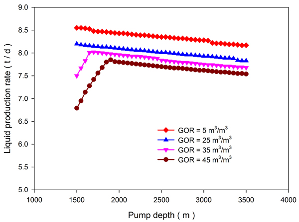
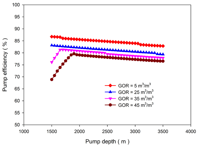
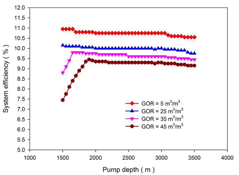
Figs. (5-7) show the effects of the pump depth and produced gas-to-oil ratio on the production rate, pump efficiency and system efficiency for a stroke of 1.23 m, a speed of 8 rpm and a pump diameter of 32 mm. For higher produced gas-to-oil ratios, the production rate, pump efficiency and system efficiency exhibit an increasing-decreasing change as the pump depth increases. However, for lower produced gas-to-oil ratios, these parameters all decrease as the pump depth increases. As the pump depth increases, the gas effect decreases and the pump efficiency increases. However, the pressure difference between the pump inlet and pump outlet increases, which accelerates the pump leakage and leads to a lower pump efficiency. For lower produced gas-to-oil ratios, the pump efficiency is mainly affected by pump leakage. For a constant pump depth, larger produced gas-to-oil ratios produce larger gas effects and, subsequently, lower pump efficiencies. Therefore, the pump efficiency is a comprehensive result of gas and leakage. For a certain produced gas-to-oil ratio, there exists a reasonable range for the pump depth.
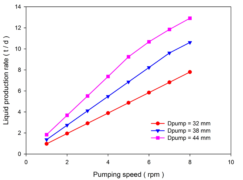
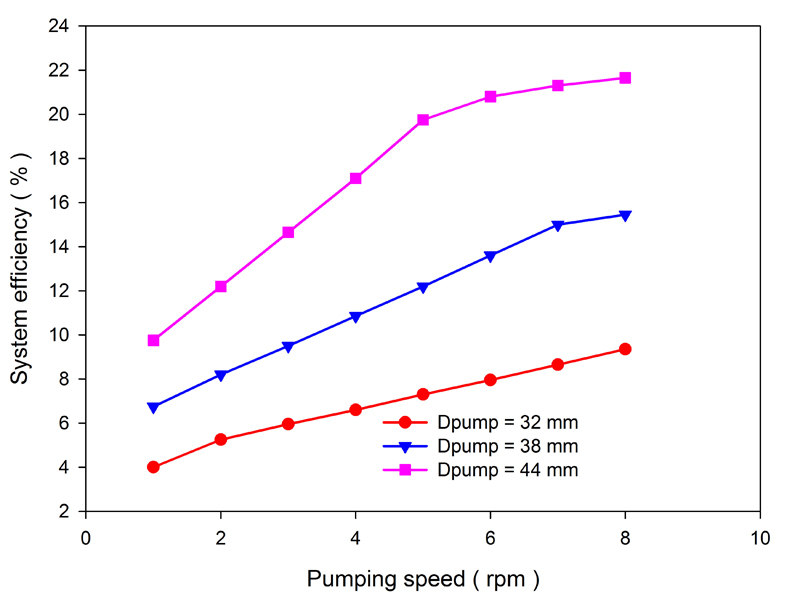
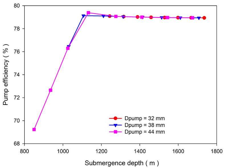
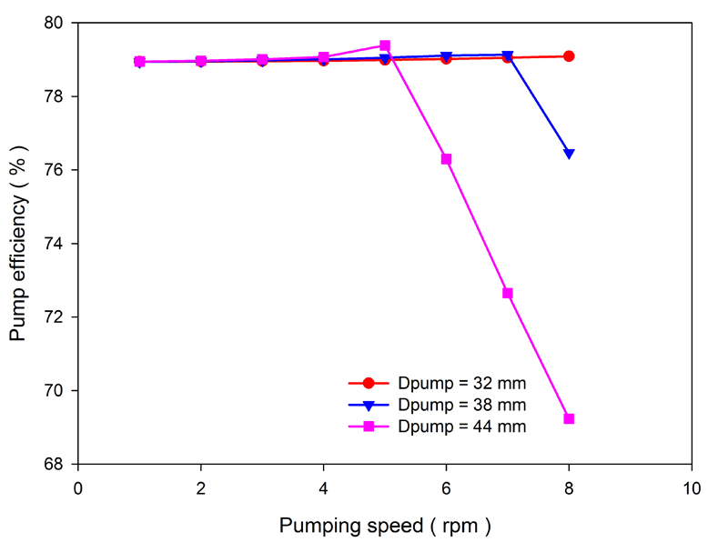
Figs. (8-10) show the effects of pump diameter and pumping speed on the production rate, pump efficiency and system efficiency for a stroke of 1.23 m, a pump depth of 2000 m and a produced gas-to-oil ratio of 45 m3/m3. As the pump diameter and pumping speed increase, so does the production rate. Correspondingly, as the pump submergence depth decreases, the effective lifting head and hydraulic power increase. The system efficiency also increases when the working frequencies of the downhole linear motor during the upstroke and downstroke remain unchanged. As the pumping speed increases, the pump submergence depth decreases, the gas and leakage effects increase and the pump efficiency decreases. Fig. (11) shows changes in the pump efficiency as a function of pump submergence depth. We see that the pump efficiency increases with the pump submergence depth. However, when the pump submergence depth exceeds a certain range, the variation in pump efficiency becomes very small. Thus, increasing the pump submergence depth excessively is not necessary.
| Parameter | Value |
|---|---|
| Reservoir pressure/MPa | 35.32 |
| Reservoir depth/m | 3617 |
| Reservoir temperature/oC | 88.41 |
| Tubing inner diameter/mm | 76 |
| Tubing outer diameter /mm | 88.9 |
| Casing inner diameter /mm | 121.36 |
| Casing outer diameter /mm | 139.70 |
| Downhole linear motor | WFQYDB 114-1140-(30~50) |
| Water cut/dimensionless | 0.148 |
| Oil specific density/ dimensionless | 0.839 |
| Water specific density/dimensionless | 1.015 |
| Gas specific density/dimensionless | 0.65 |
| Bubble pressure/MPa | 5.81 |
| Productivity Index/t/d.MPa | 1.86 |
| Wellhead tubing pressure/MPa | 0.1 |
| Wellhead casing pressure/MPa | 0.1 |
4.2. Case Study
The Ma 2 well block is located in the northern region of Manas Lake in the Junggar basin. The oil-bearing layer includes the Triassic Baikouquan Formation and the Permian Wuerhe Formation. The formation is a lithologic reservoir without bottom water and edge water. The Wuerhe formation is a very poor reservoir with secondary pores, a fine throat, low porosity and ultralow permeability. The porosity changes from 6.0% to 14.23% and the average porosity is 8.14%. The permeability ranges from 0.36×10⁻³ μm2 to 1763.4×10-3 μm2 and the average permeability is 6.42×10⁻³ μm2 [18, 19].
The X-I well is a producer that was completed at 3621 m in the Wuerhe Formation. It was taken into production as a flowing well after a hydraulic fracturing treatment in July 2013. The reservoir pressure decreased quickly due to an insufficient supply of formation energy. The current reservoir pressure is 31.43 MPa, and the bubble pressure is 5.81 MPa. Table 3 lists its production data when operated with a conventional sucker rod pumping system. The tubing, casing and motor data are shown in Table 2.
Under these working conditions, the pump efficiency is 38.9% and the power consumption associated with lifting one ton of liquid is 134.75 kWh. The system efficiency is less than 1%. The reasons for this are significant stroke loss and an unsuitable pump depth. In December 2017, a RDD-ESPP lifting system was installed in this well. The developed models and optimal working parameter selection method are used to optimize the most appropriate working parameters for this well. The downhole linear motor used for this well is a WFQYDB 114-1140-(30~50). Table 4 shows the design results for an allocated production rate of 3 t/d and a stroke of 1.23 m.
| Parameter | Value |
|---|---|
| Pump depth/m | 3430 |
| Pump diameter/mm | 32 |
| Stroke/m | 1.5 |
| Speed/rpm | 4 |
| Wellhead tubing pressure/MPa | 0.1 |
| Wellhead casing pressure/MPa | 3.9 |
| Production rate/(t/d) | 2.7 |
| Water cut/dimensionless | 0.148 |
| Gas-to-oil ratio/(m3/ m3) | 5 |
| Working liquid level in casing-tubing annulus/m | 224 |
| Pump Depth /m |
Pumping Speed /rpm |
Pump Diameter /m |
Production Rate /(t/d) |
Pump Efficiency /% |
System Efficiency /% |
Power Consumption by Lifting One Ton of Liquid /(kWh/t) |
|---|---|---|---|---|---|---|
| 1950 | 2 | 38 | 3 | 86.58 | 5.44 | 81.22 |
| 2000 | 2 | 38 | 2.98 | 86.01 | 5.4 | 81.76 |
| 2050 | 2 | 38 | 2.98 | 85.87 | 5.39 | 81.89 |
| 2100 | 2 | 38 | 2.97 | 85.75 | 5.39 | 82 |
| 2150 | 2 | 38 | 2.97 | 85.65 | 5.39 | 82.11 |
| 2200 | 2 | 38 | 2.97 | 85.54 | 5.38 | 82.2 |
| 2250 | 2 | 38 | 2.96 | 85.45 | 5.39 | 82.3 |
| 2300 | 2 | 38 | 2.96 | 85.35 | 5.39 | 82.39 |
| 2350 | 2 | 38 | 2.96 | 85.26 | 5.39 | 82.47 |
| 2400 | 2 | 38 | 2.95 | 85.17 | 5.39 | 82.56 |
| 2450 | 2 | 38 | 2.95 | 85.08 | 5.39 | 82.65 |
| 2500 | 2 | 38 | 2.95 | 85 | 5.39 | 82.73 |
| 3200 | 3 | 32 | 3.08 | 83.44 | 3.82 | 118.62 |
| 3250 | 3 | 32 | 3.08 | 83.36 | 3.82 | 118.74 |
| 3300 | 3 | 32 | 3.08 | 83.27 | 3.82 | 118.86 |
| 3350 | 3 | 32 | 3.08 | 83.19 | 3.82 | 118.98 |
| 3400 | 3 | 32 | 3.07 | 83.11 | 3.81 | 119.1 |
| 3450 | 3 | 32 | 3.07 | 83.03 | 3.81 | 119.22 |
| 3500 | 3 | 32 | 3.07 | 82.95 | 3.81 | 119.33 |
The pump efficiency and system efficiency can be improved largely by adopting this new RDD-ESPP lifting system and changing the pump depth. For the same stroke, speed and pump diameter, we observed that a large increase in the pump depth could not significantly improve the lifting efficiency. Considering that increasing the pump depth will increase the tubing and cable cost, a pump depth of 1950 m, a pump diameter of 38 mm, a stroke of 1.23 m and a speed of 2 rpm were adopted. The currents and frequencies for the upstroke and downstroke were 25 A and 12 A, and 8 Hz and 20 Hz, respectively. Using these optimized working parameters, a daily production rate of 2.8 t/d, a power consumption of 86.39 kWh per ton of liquid and a system efficiency of 4.97% were achieved in the X-I well after the RDD-ESPP lifting system was installed. The lower system efficiency is due to the installation of an unsuitable motor due to limitations of the supply of motors in the field. The daily power consumption decreased from 363.8 kWh to 241.9 kWh after optimization and a power savings rate of 33.5% was realized. The pump efficiency increased from 38.9% for the sucker rod pumping system to 80.5% for the RDD-ESPP lifting system. Compared with other field applications by changing the sucker rod pumping system to an RDD-ESPP lifting system, average pump efficiency improvements such as 44.3% in the Jinlin oilfield (Zhang, 2015) and 60.6% in Zhengting oilfield (Wang, 2012), 22% in the Changqing oilfield (Zheng et al., 2013) and 45.64% in the Daqing oilfield (Wang et al., 2007) were achieved. The application of the RDD-ESPP lifting system in the X-I well is demonstrated to have a remarkable energy-savings effect. Additionally, errors between the calculated results and the actual measurements of the production rate, pump efficiency, system efficiency and power consumption are 7.14%, 7.55%, 9.46% and -5.98%, respectively. These results show that the proposed method can be used to select optimal operating parameters for a RDD-ESPP lifting system and analyze its working state.
CONCLUSION
A reciprocating direct-drive electric submersible plunger pump lifting system is a new rodless artificial lifting system with a higher pump efficiency and a lower power consumption. Based on the working principle of this system, mathematical models for the wellbore temperature distribution, lifting load, pump efficiency, system efficiency and tubing strength validation are developed. Field applications were implemented based on the proposed method and the following conclusions can be drawn:
(1) The RDD-ESPP lifting system completely eliminates the problem of eccentric wear between the tubing and the sucker rod that occurred in conventional sucker rod pumping systems. This technology can be used in vertical, deviated and horizontal wells. Moreover, it has a lower power consumption and a higher system efficiency than a conventional sucker rod pumping system due to the use of an intermittent power supply.
(2) The pump efficiency of the RDD-ESPP lifting system is mainly affected by the gas and leakage. As the pump submergence depth decreases, the gas effect in the pump and the pressure difference across pump increase, which causes the pump leakage to increase and the pump efficiency to decrease. When the pump submergence depth increases to a certain range, it is no longer a significant factor in terms of pump efficiency when continually increasing the pump submergence depth.
(3) The production of a low-production and deep oil well was analyzed and optimized. The field application shows that a 33.5% power savings rate and a 41.6% pump efficiency improvement are possible after optimization. The energy savings is remarkable.
(4) The errors between the calculated results and the actual measurements in terms of the production rate, pump efficiency, system efficiency and power consumption are less than 10%. The proposed method described in this work can be used to optimize and analyze an RDD-ESPP lifting system.
CONSENT FOR PUBLICATION
Not applicable.
AVAILABILITY OF DATA AND MATERIALS
Not applicable.
FUNDING
CNPC Major Scientific and Technological Special Project (No. 2017E-04-14) and the National Natural Science Foundation of China (No. 51674278) for their financial support.
CONFLICT OF INTEREST
The authors declare no conflict of interest, financial or otherwise.
ACKNOWLEDGEMENTS
The authors would like to thank the CNPC Major Scientific and Technological Special Project and the National Natural Science Foundation of China for their financial support.