All published articles of this journal are available on ScienceDirect.

The Design of an Integrated Crude Oil Distillation Column with Submerged Combustion Technology
Authors Info & Affiliations
Abstract
Objective:
Generally, Petroleum refineries are put in place to convert or refine unprocessed crude oil into more useful products using both physical separation and chemical conversion processes. Albeit, different refining unit are subsets of the physical separation category. The atmospheric and vacuum distillation unit seems to be more prominent. Conventionally, the crude atmospheric residue cannot be further heated in an atmospheric condition due to: coke formation, pipes plugging, thermal cracking and straining of the furnace. A vacuum distillation column is therefore required.
Methods:
This study, therefore, focuses on the limitations, “over straining of the furnace to provide the necessary heat” and “non-reliance on the additional re-boiler since it only acts as a heat exchanger”. An integrated distillation column with a capacity of 10,000 barrel per day was therefore designed for the concurrent production of all distillate cuts.
Results:
This was achieved through the introduction of a submerged combustion zone at the stripping section of the column where Naphtha was utilized as the source of fuel. Verification of this approach was also conducted using Autodesk invention software and a finite element analysis tool to evaluate both thermal and computational fluid analysis impact. Overall, all derived distilled products met the American Society for Testing and Material Standard Table 6.
1. INTRODUCTION
1.1. Background Knowledge
Generally, Petroleum refineries are put in place to convert or refine unprocessed crude oil into more useful products using both physical separation and chemical conversion processes [1]. Although the physical separation processes separate the crude oil mixture without altering the chemical characteristics of its components, the chemical conversion processes which are either thermal or catalytic help to upgrade or improve lower value fractions into products better adapted to the markets [2, 3].
The physical separation processes are always based on the differences in certain physical properties such as boiling and melting points, adsorption affinities on a certain solid and diffusion through certain membranes [1, 4]. Albeit, different refining units fall into this category. The atmospheric and vacuum distillation unit seems to be more prominent.
Distillation is simply the separation of compounds with varying vapour pressures at any given temperature or the physical separation of a mixture into two or more fractions with different boiling points [5]. Crude oil distillation is therefore, the physical separation of oil of little or no value to significant products and components via boiling.
The atmospheric distillation column is believed to be the biggest unit in a petroleum refinery as it can process up to 200,000 barrels of oil per day with a height of 338 feet [5]. This process is always carried out at a pressure slightly above atmospheric pressure to separate the crude oil feed into different fractions based on their difference in boiling points. These fractions include: Methane, Ethane and Propane mixtures, Liquefied Petroleum Gas (LPG), Naphtha’s/ Gasoline Fractions, Kerosene/Aviation Turbine Fuel, Light Gas Oil, Heavy Gas Oil and Reduced Crude Oil which are further processed for possible finished works or as intermediate feedstocks as shown in Table 1 below.
The success of any distillation separation process largely depends on some auxiliary units (series of heat exchangers, de-salter, and furnace) which the crude must pass through before the distillation column. The heat exchangers make use of hot vapour’s streams from the condenser, Pump Around (PA) circuit streams and the distilled products to preheat the incoming cold crude oil that is fed [6]. Although the desalting process remains an optional stage, it helps to remove all form of salts (mainly chlorides and sulphates of sodium, calcium, and magnesium) via emulsion and de-emulsion [7, 8]
The residue from the atmospheric distillation column cannot be further heated to their boiling points at atmospheric pressure due to: (i) severe thermal cracking of the oil, (ii) overstraining (fatigue stress) on the furnace to provide the necessary heat needed (being the major source of heat), (iii) un-reliance on the additional re-boiler since it only acts as a heat exchanger, (iv) fouling on both the distillation column /heating medium and a future decline of efficiency from the heater [9]. A vacuum distillation column is therefore used to distill at a lower pressure at the expense of an additional cost of column, re-boilers, condensers and pressure ejectors.
The vacuum distillation process occurs at a reduced density and absolute pressure of 25-40 mmHg (millimeter mercury) with a temperature range of 340-610°C. Its major objective is to increase the number of middle distillates, produce lubricating oil base stocks and asphalt. The vacuum distillation unit consists of the vacuum furnace, vacuum tower, vacuum producing unit and superheated steam. Superheated steam is important here as it tends to decrease the partial pressure of the hydrocarbons to 10mmHg or less and reduces coke formation in the furnace tubes. The vacuum producing unit which helps to suck lighter hydrocarbons is produced by ejectors or a combination of ejectors and a liquid ring pump [10]. The ejector works by recompressing the gases and speeding them up (venture effect) through a nozzle while the ling ring pump works in a similar manner to an eccentric rotor gas compressor [11].
Although a lot of constraints has been identified on why further heating of the crude oil above 380○ C cannot be carried out in an atmospheric column; over straining on the furnace to provide the necessary heat needed and un-reliance on the additional re-boiler since it only acts as a heat exchanger will be the focus and concern of this paper.
A profound solution to this issue will help eradicate the need for a vacuum distillation column which ultimately reduces operational cost. The solution will also help tackle issues associated with modular crude refining.
1.2. Submerged Combustion
The principle behind submerged combustion technology was used firstly by See et al. [12], where he defined the technology as a combustion process that occurs beneath the surface of a liquid. Fuel and air are mixed together to produce high-temperature flue gas which is discharged below the surface of the liquid and passed upward through the liquid to be distilled. The direct contact between the hot flue gas and the liquid results in unusual high heat transfer rates and a thermal efficiency of ≥ 90% [13].
| Column | Fraction | Temperature (OC) | Carbon Range | Uses | Disposition |
|---|---|---|---|---|---|
| Atmospheric Column |
Fuel Gases | <40 | C1-C2 | Fuel | LPG |
| LPG | C3-C4 | Domestic Fuel | |||
| Straight Run Gasoline | 20-90 | C6-C10 | Gasoline Pool | Hydro-treating Unit | |
| Naphtha (Medium and Heavy) | 130-180 | C6-C10 | Catalytic Reforming and aromatic plant feedstock. Steam cracker, synthesis gas manufactured | ||
| Kerosene | 150-270 | C11-C12 | Aviation turbine fuel, Domestic fuel, LAB feedstock (paraffin source) | Hydro-Treating Unit/ Merox Treating Unit | |
| Light Gas Oil | 230-320 | C13-C17 | Low-speed diesel component | Fluid Catalytic Cracking Unit | |
| Heavy Gas Oil | 320-380 | C18-C25 | High-speed diesel component | ||
| Atmospheric Residue | Vacuum Distillation Unit | ||||
| Vacuum Column | Light Vacuum Gas Oil | 370-425 | C18-C25 | Feed to Fluid Catalytic Cracking (FCC)/ Hydrogen Cracking Unit (HCU) | Hydro- Treating Unit |
| Heavy Vacuum Gas Oil | 425-550 | C26-C38 | Fluid Catalytic Cracking Unit | ||
| Vacuum Residue | >540 | >C38 | Bitumen/ Vis-breaker feed | Coking |
See et al. [14], went further to give us the characteristics of the submerged combustion burner, which includes: simplicity, rigidity and durability in construction but rigidly and durably constructed. It comprises of an outer cylindrical elongated tubular casing housing an inner tubular elongated casing mainly for ignition purposes. For corrosion and safety purposes, the metal part of the burner is constructed with Hastelloy C (58-60% nickel, 17% molybdenum and 15% chromium) and Hastelloy D (85-90% nickel and 3% copper).
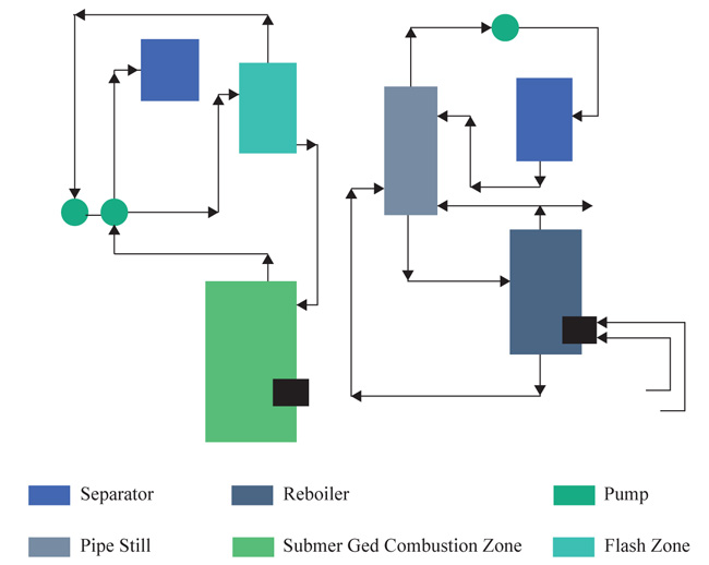
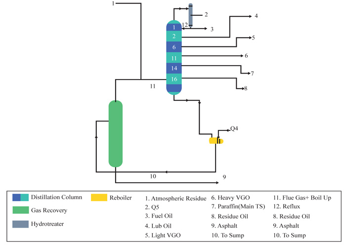
Saxton et al. [13], successfully produced high distillate cut points (asphalt) without the use of a vacuum distillation tower. This process was carried out with the use of Submerged Combustion Technology. As shown in Fig. (1), the atmospheric residue passes through a flashing chamber housing the submerged combustion burner. The submerged combustion burner is regulated to a certain temperature and pressure depending on the preferred distilled cuts. In this context, a temperature of (317-426OC) and pressure of 172.3Kpa was used for asphalt. They also illustrated that it is possible to direct the atmospheric residue to a pipe still where side streams can be withdrawn while the heavier components are directed to a re-boiler with a submerged combustion zone.
Although submerged combustion technology has not readily gained ground in the crude oil refining sector, this technology has successfully been applied in other areas. These areas include mining (heap leaching, decommissioning and slurry heating), forestry (log ponds), waste-water treatment (sludge and pasteurization process), carpet manufacturing, glycol recovery, municipal swimming pools and commercial laundries.
1.3. Aim and Objectives
The aim of this study is to design a single distillation column (10,000 barrels per day) that can simultaneously distill crude oil under both atmospheric and vacuum conditions. This will be achieved via the following objectives
-
 To design a 10,000bpd atmospheric distillation column under ideal condition, using Bonny Medium as the case study
-
To design the inclusion of a submerged combustion chamber at the sump section of the distillation column
-
To optimize the usage of Naphtha as the source of fuel for the submerged combustion process.
-
To verify the feasibility of this approach using Solid Work Simulation software
2. METHODOLOGY
Generally, a process design problem involves the evaluation of design parameters for a given process condition while a typical process simulation problem involves the evaluation of output variables as a function of input variables and design parameters. In a typical binary distillation operation, the use of Mc- Cable Thiele Diagram is adopted for process design calculations and a system of equations whose total number does not exceed 20. However, for multi-component systems, adopting a graphical procedure is ruled out; Fenske, Underwood and Gilliland (FUG) method can serve as an alternative. Alternatively, for a rigorous design of multi-component distillation column, commercial process simulators (HYSYS) can be used to reduce the time and seems more reliable than the numerous calculations done by hand. It also allows easy modification of operating conditions. It works via different equation of states; notable ones include the Soave Redlich Kwong (SRK) and Peng Robinson Equation of States (PR-EOS).
| - | I.T(OC) | F.T(OC) | Sulphur By Weight (%) | K.V(cSt) @37.8(OC) |
- | I.T(OC) | F.T(OC) | Sulphur By Weight (%) | K.V(cSt) @37.8(OC) |
|---|---|---|---|---|---|---|---|---|---|
| Whole Crude | IBP | FBP | 0.12 | 3.21 | Cut 11 | 303.5 | 336.5 | 0.13 | 8.74 |
| Cut 1 | IBP | 8.9 | 0 | 0.43 | Cut 12 | 336.5 | 369.4 | 0.15 | 16 |
| Cut 2 | 8.9 | 40 | 0 | 0.42 | Cut 13 | 369.4 | 402.4 | 0.18 | 31.74 |
| Cut 3 | 40.0 | 72.9 | 0 | 0.45 | Cut 14 | 402.4 | 435.3 | 0.21 | 66.45 |
| Cut 4 | 72.9 | 106 | 0 | 0.56 | Cut 15 | 435.3 | 468.2 | 0.24 | 154.03 |
| Cut 5 | 106 | 139 | 0 | 0.71 | Cut 16 | 468.2 | 501.2 | 0.28 | 367.73 |
| Cut 6 | 139 | 172 | 0.01 | 0.93 | Cut1 7 | 501.2 | 534.1 | 0.32 | 1099.2 |
| Cut 7 | 172 | 204.7 | 0.02 | 1.28 | Cut 18 | 534.1 | 567.1 | 0.37 | 3221 |
| Cut 8 | 204.7 | 237.6 | 0.04 | 1.93 | Cut 19 | 567.1 | 600 | 0.41 | 10623 |
| Cut 9 | 237.6 | 271 | 0.07 | 3.05 | Cut 20 | 600 | 650 | 046 | 71637 |
| Cut 10 | 271 | 303.5 | 0.10 | 5.07 | Cut 21 | 650 | FBP | 0.51 | 364753 |
2.1. Crude oil Characterization
Characterization of Bonny Medium crude assay Table 2 using Aspen Hysys Simulation Software version 8.6 was done based on their true boiling points. This was carried out to give the average properties of the various products.
2.2. Determination of Operating Parameters
With a design capacity of 10000bpd, a fixed temperature of 358.31oC and an operating pressure of 700kpa of crude entering the main distillation column. Aspen Hysys Simulation Software version 8.6 was used to determine other necessary operating parameters and properties of initial distilled products. Hysys Simulator was used to show the individual product trays coming out from the distillation column. Although simulation software was used [5,15,16, 17], explains in details the manual calculation procedure.
2.3. Design of the Integrated Distillation Column
To calculate the height of the column taking into consideration accumulation of internal build up, the following equation is used based on Mochamad et al [17]:
 |
(1) |
 |
(2) |
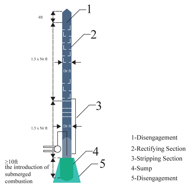
The entire length of the integrated column has been deduced as 21.03meters (69ft). This whole design will be cumbersome if treated as just one column in this work. Hence, the column design will be broken down into different sections for easy analysis and description as shown in (Fig. 2).
2.3.1. Disengagement Section
The disengagement height is the added height to the original height of the calculated column. It is usually 4ft for most columns [18].
The flow rate through nozzles is calculated via
 |
(3) |
Where q - flow rate (m3/s), C - flow coefficient, A - cross section area (m2), ΔP - pressure drop (Pa) and ρ – density (kg/m3).
The diameter is expressed as
 |
(4) |
With the aid of the Autodesk Inventor Professional 3D CAD software design tool, the disengagement section is designed and shown
2.3.2. Rectifying Section
This is known as the largest portion of the entire distillation column and also the section above the feed tray. With a tray spacing of 1.5ft and a total number of 30 trays, the total length of this section and the corresponding outlet nozzles for the production of the different products of the column were deduced using equation (1).
A computer-aided design of this section illustrating the tray position with the estimated height was also shown in the result section.
2.3.3. Stripping Section
The stripping section of this design providentially possesses the same diametric nature as the rectifying section. The remaining height from the schematic distillation unit goes to the stripping unit. The height is also calculated using equation (1)
2.3.4. Sump/Submerged Section
Generally, the sump section serves the purpose of level control and acts as a phase barrier between the liquid being evacuated and the vapour being sealed. The sump section also provides an enabling environment for a submerged combustion burner to be introduced. Since the stripping section would contain the submerged combustion chamber, some portion of the height will be used to accommodate the installation of sieve trays to aid in the heat and mass transfer of the vaporized atmospheric residue. The Autodesk Inventor Professional CAD software and solid work simulation software was used to show the interior part of the submerged combustion process.
2.4. Combustion of Flue Gas
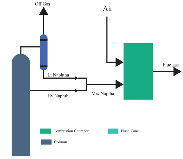
In several cases, the process fuel type used is LPG but since the bonny medium shows low quantity of off-gas and LPG standing as one of the arms of the profit margin components, it is advised that the fuel type be a low demandable, controllable fuel. From the streams of products, the best fuel to utilize for the submerged combustion is Naphtha. This will not affect the quantity of other marketable products, and thus will be used for the sole purpose of recovering other heavier components
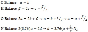
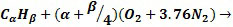
To combust Naphtha, they will follow the general hydrocarbon combustion model as shown below. Although air is used as the oxygen source, nitrogen present in the air is also added to show the composition of the resultant flue gas O2(Oxygen), N2(Nitrogen), CO2(Carbon Dioxide) and H2O(Water).
 |
(5) |
 |
 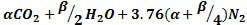
|
(6) |
Due to the homogeneity of the naphtha fuel, it would be cumbersome to perform a manual calculation; hence the combustion was performed using Hysys software. In this simulation, the light and heavy naphtha are predominantly mixed in a mixer and then it is charged in a conversion reactor which acts as the engine as shown in Fig. (3) below. At an optimal scheme, the operating conditions for the air to fuel mixture are highlighted.
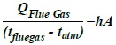
Scientifically, the relationships in the submerged chamber are expressed as equation (7) and (8) below:
Heat rejected from flue gas = the heat gained in the atmospheric residue.
 |
(7) |
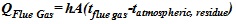 |
(8) |
Where Q = heat rejected or gained (j), h =convective heat transfer coefficient of the flue gas (w/m2k), A= area of the liquid covered (m2), tflue gas = temperature of the flue gas (K) and tatmospharic, residence = temperature of the atmospheric residue (K)
 |
From the simulation carried out on the engine with the cross section of the column taken, we determined the convective heat transfer coefficient of the flue gas in conjunction with the area of the atmosphere residue to provide us with the overall heat transfer coefficient.
This singular approach is not an accurate method as it only tells us the exact occurrence at a region not a step by step impact. A more précised means is using a Finite Element Analysis (FEA) tool which analyzes both Computational Fluid Dynamics (CFD) and thermal effect OC
2.5. Verification Approach Using the Finite Element Analytical Approach
The verification process was carried out using the computational fluid dynamics tool. It carries out an advanced simulation using numerical analysis and algorithm to solve and analyze fluid dynamics problems.
The process was carried out via the following steps:-
-
Inventor design of the stripping and submerged combustion section
First, the model which is an evolvement of length in the x, y and z-axis is being modelled via the Computer Aided Designing (CAD) software called the Autodesk Inventor. - Discretizing the model using the finite element volume approach
- Boundary conditions and solutions
The boundary conditions involve defining the operating condition of the whole system and their step by step impact using the Finite Elemental Analysis (FEA) Structural tool . After the combustion of the naphtha fuel in the combustion engine, the flue gas leaving temperature, pressure, and flow rates are noted and are utilized in the model. The temperature of the atmospheric residue at the base of the distillation, the density of both the flue gas and the atmospheric residue together are also needed so as to have a very close proximity with the real fluids.
The convective heat transfer coefficient will also be used to initiate the heat transfer process between the fluids. This is done to determine the propagation of the heat flux during the mixing of the two fluids. The propagation can be calibrated in terms of the level of heat movement towards the lower temperature fluid which in this case is the atmospheric residue.
2.6. Separating Membrane Design
The rectifying section, as well as the stripping section, is being separated by a slim sheet of stainless steel. The solid work simulation software (FEA structural tool) was used to the temperature variation around it thereby confirmimg the viability of this approach.
2.7. HYSYS Simulation of the Integrated Distillation Column
A total simulation of the integrated distillation column was done using HYSYS to determine the overall viability of this approach and also analyze the physical and chemical properties of all distilled products. The initial operating parameters (10000bpd design capacity, fixed temperature of 358.31oC and operating pressure of 700kpa of crude entering the main distillation column) were used. The heat generated at the exhaust of the combustion burner served as re-boiler of another column since HYSYS does not have a submerged combustion burner in its package.
3. RESULTS AND DISCUSSION
3.1. Characterization of Bonny Medium Crude Oil
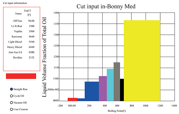
Bonny medium crude characterized based on its true boiling points produces 0.02m3, 0.01m3, 0.085m3, 0.12m3, 0.14m3, 0.175 m3, 0.1m3and 0.365 m3 liquid volume fraction of off gas, light naphtha, heavy naphtha, kerosene, light diesel, heavy diesel, AGO and residue respectively as shown in Fig. (4) The values in percentage forms are 2% off gas, 9% naphtha, 12% kerosene, 41% diesel and 36% atmospheric residue of the total liquid volume fraction. These values represent the maximum liquid volume fraction of the different distillate that can be got from the crude at an ideal condition.
3.2. Column Operating Parameters and Distilled Products Properties
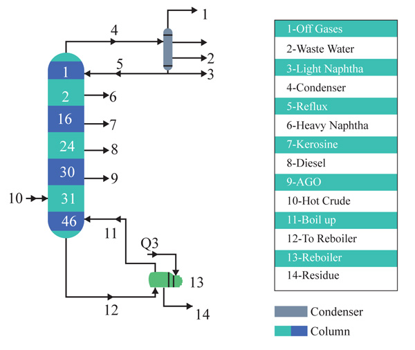
Tables 3 and 4 show the operating conditions of both the distillation column and distilled products. Although the distillation columns has 46 trays, Atmospheric Gas oil is distilled at tray 30. The remaining 16 trays give room for the Atmospheric residue to be broken down into other products when a submerged combustion burner is inserted into the stripping section of the column. Fig. 5 below shows the distillation column showing the various products tray.
3.3. Design of the Integrated Distillation Column
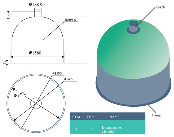
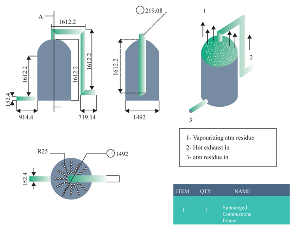
3.3.1. Disengagement Section
The disengagement height is the added height to the original height of the calculated column. It is usually 4ft for most columns and aids the disengagement of the top column for maintenance work, maintains separation efficiency and avoids intensive liquid entrainment in the equipment downstream and the projection of the outlet nozzle for off gas production as well as the reflux chamber Fig. (6) [18].
From previous deductions, ∆P = 1.11kpa (0.1612psi), q = 369.9ft2⁄sec(0.1027ft3 ⁄ sec) and p = 0.156 lb/ft3 .
The flow rate through nozzles is calculated via
 |
Where q - flow rate (m3/s), C - flow coefficient, A - cross section area (m2), ΔP - pressure drop (Pa)and ρ – density (kg/m3),
A = 0.00277ft2 (0.00026m2)
The diameter is expressed as
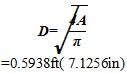 |
| Parameters | Value | Parameters | Value |
|---|---|---|---|
| Column Diameter | 1.52m | Constant Pressure Drop down the Tray | 1.11Kpa |
| Down-comer Area | 0.12m2 | Constant Stage Efficiencies | 1 |
| Reflux Ratio | 4 | Number of Trays | 46 |
| Condenser Duty | 948.88J/s | Tray Diameter | 1.50m |
| Condenser Pressure | 100kpa | Tray Spacing | 0.46m |
| Condenser Temperature | 46.29 OC | Tray Volume | 0.89m3) |
| Re-boiler Pressure | 150Kpa | Weir Height | 0.05m |
| Re-boiler Temperature | 400.01 OC | Weir Length | 1.20m |
| Steam | Mass Flowrate (kg./s.) | Volume Flow Rate (m3/s.) | Draw Off Temperature (OC) | Draw Off Tray |
|---|---|---|---|---|
| Off Gas | 1.76 | 0.0029 | 46.29 | 1 |
| Light Naphtha | 0.02 | 0.000031 | 46.29 | 1 |
| Heavy Naphtha | 0.01 | 0.000012 | 76.53 | 2 |
| Kerosene | 4.41 | 0.0057 | 139.13 | 16 |
| Diesel | 5.32 | 0.0064 | 273.67 | 24 |
| AGO | 1.15 | 0.0027 | 340.02 | 30 |
| CONDITIONS | |||||
|---|---|---|---|---|---|
| Name | Unit | Naphtha | Air |
Dummy Liquid |
Flue Gas |
| Vapour | 0.065 | 1 | 0 | 1 | |
| Temperature | F | 129.5064 | 77 | 783.8686 | 783.8686 |
| Pressure | psia | 14.5038 | 16 | 14.5038 | 14.5038 |
| Molar Flow | lbmol/hr | 2.9015 | 6.5 | 0 | 9.4714 |
| Mass Flow | lb/hr | 231.9311 | 188.175 | 0 | 420.1061 |
| Standard Ideal Liquid Volume Flow |
USGPM | 0.6728 | 0.4273 | 0 | 1.0924 |
| Molar Enthalpy | Btu/lbmole | 7.48E+004 | -3.914 | -2.29E+04 | -2.29E+04 |
| Molar Entropy | Btu/lbmole F |
20 | 28.06 | 49.97 | 49.97 |
| Heat Flow | Btu/hr | -2.17E+005 | -2.54E+01 | 0 | -2.174E+05 |
With the aid of the inventor design tool, the disengagement section is designed and shown (Fig. 6).
3.3.2. Rectifying Section
With a tray spacing of 1.5ft and a total number of 30 trays, the total length of this section and the corresponding outlet nozzles for the production of the different products of the column is shown below
- Total length of the rectifying sectioned column: 1.5 x Nr (Tray Location)
= 1.5 X 30 = 45f - The reflux stream (Light Naphtha), this is found at the 1st tray
1.5 X 1 = 1.5ft - The Heavy Naphtha stream, this is found at the 2nd tray
1.5 X 2 = 3ft - The Kerosene stream, this is found at the 16th tray
1.5 X 16 = 24ft - The Diesel steam that is found on the 24th tray
1.5 X 24 = 36ft - The AGO steam that is found on the 30th tray
1.5 X 30 = 45ft
Having a total of 30 trays due to the trays above the feeding line, this section comprises of the reflux inline stream, the heavy naphtha production, kerosene stream, diesel stream and the AGO stream. It is known to be the largest portion of the entire distillation column. Fig. (7) shows the inner structure of the rectifying section also designed with the inventor software illustrating the tray position with estimated height
3.3.3. Stripping Section
The stripping section of this design providentially possesses the same diametric nature as the rectifying section. It elaborately carries the heavier components left after the AGO production which happens to be the residual crude down the column to the sump.
The remaining height from the schematic distillation unit goes to the stripping unit:
• Stripping section Height = 1.5 x Ns (Number of Trays)
= 1.5 x 16
= 24ft
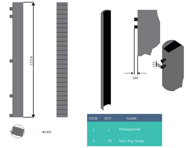
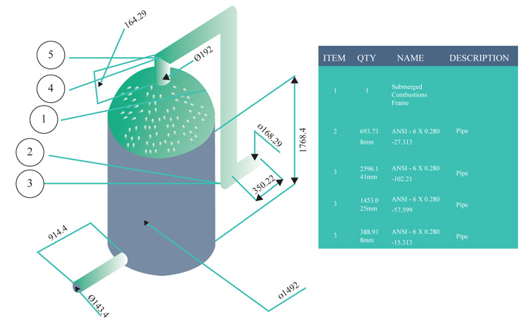
3.3.4. Sump/ Submerged Section Design
Since the stripping section would contain the submerged combustion chamber, some portion of the height will be used to accommodate the installation of sieve trays to aid in the heat and mass transfer of the vaporized atmospheric residue. A mixture of the high-temperature fuel and the air is directly discharged into the atmospheric liquid. This direct contact creates increased agitation, turbulence, enthalpy, and entropy. All these factors help to raise the temperature of the crude to the boiling points of the gas oils that could not have been achieved via atmospheric pressure and re-boiler heat alone. The rising vapour is then allowed to pass through the sieve tray and at the right temperatures the products will separate out leaving the residue as asphalt. Since this is still an experimental setup, it will include no strippers or refluxes.
The vaporized vapor is meant to be regulated not to exceed the temperature of asphalt. Hence, the temperature of the vapor will contain constituents involving gas oils and paraffin waxes. These will be regulated through the corresponding sieve plates above the column. At varying length within the column, the desired vacuum distillation products will be recovered at the standard temperature. Figs. (8 and 9) shows the interior part of the submerged combustion zone with the use of Autodesk Inventor Professional CAD software and solid work simulation software.
Conventionally, there will be a heat transfer mechanism occurring due to the differences in temperature potential as the heat from the flue gas gradually increases the vapor pressure of the residue counter balancing with the pressure at the bottom of the column. Hence, the individual components of the atmospheric residue begin to boil gradually, vaporizing to the trays inserted in the column
The convective overall potential can then be calculated using
 |
3.3.5. Sump/ Submerged Section Design
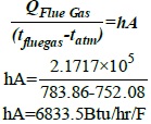
From Table 5, it is noted that the air needed to completely combust the Naphtha fuel comes into the engine at 1.103 bars (110.3KPa), 25oC (77F) and 0.4273USGPM (3.39, 1.60 liters/min). The corresponding result of the flue gas from the engine leaves at 417.7oC, 100.04KPa, 1.0924USGPM (8.76) and most importantly, is the heat flow which is 2.1717 x 10⁵ Btu/hr. (exothermic). The flue gas which now acts as the energy source is submerged into the column where the atmospheric residue is held.
3.4. Verification Approach Using the Finite Element Analytical Approach
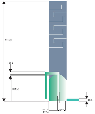
3.4.1. Inventor Design of the Stripping and Submerged Combustion Section
Model highlighting the trays above the stripping section, the stripping total height of 7315.5mm and the submerged combustion height of 1828.8mm Fig. (10).
3.4.2. Discretizing the Model using the Finite Element Volume Approach
The discretization reduces the model into smaller elements with nodes. These elements are where the fundamental equations and boundary conditions are subjected into. For a discreet setting, the meshing process takes the tetrahedral elemental structure. This element accommodates for the processing of 3D models in which the x, y and z axis can be put under consideration during the setting of the boundary conditions and the acknowledgment of their effect as shown in (Fig. 11).
3.4.3. Boundary Conditions (Solutions)
The process flow in the column was initialized with the corresponding boundary conditions (temperature, pressure and specific gravity of both the flue gas and atmospheric residue) The solutions using renowned background iterative models are the temperature distribution and the heat flux distribution. Using the fundamental principles, the simulation can be sure to perform the all the necessary iterations along the column.

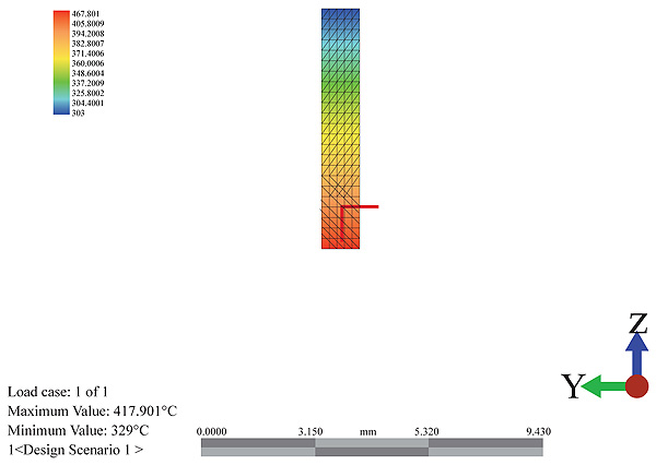
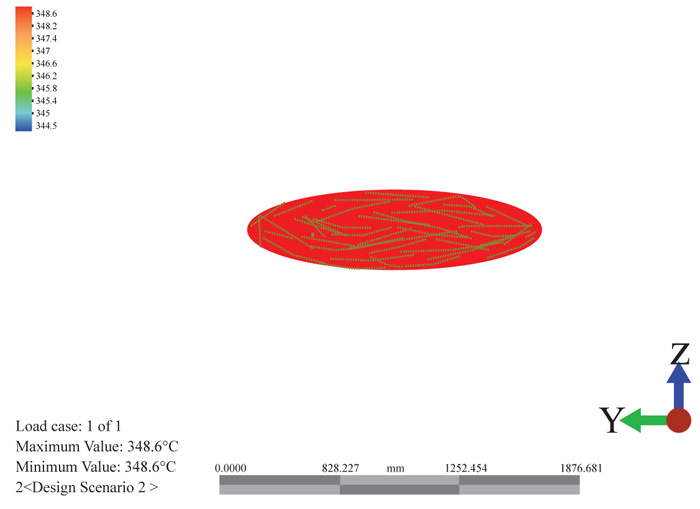
3.4.3.1. Temperature Distribution
The temperature distribution can be seen hypothetically from the color variations as shown in Fig. (12) below. The red color shows the entry of the flue gas at a temperature of 417.71oC meeting the atmospheric residue at a temperature of 400.05oC. It is seen that the temperature drops as it rises and interacts with the trays of the column. The temperature profile along the meshes shows a significant drop along the height of the column. This drop is associated with the heat received by the atmospheric residue and the gradual drop as it rises. The temperature rises from the exhaust temperature to the temperature of the atmospheric residue.
There is no internally generated heat in the system and as such experiences a very gradual cooling rate. At different sections of the column, the different boiling products can be collected as side cuts. This is shown in Fig. (13) below as it suggests the estimated heights for the collection of the different products at their boiling points. Along the height of the column, the cooling curve is plotted to show the sloppy drop in temperature.
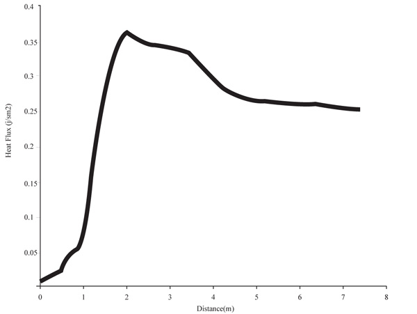
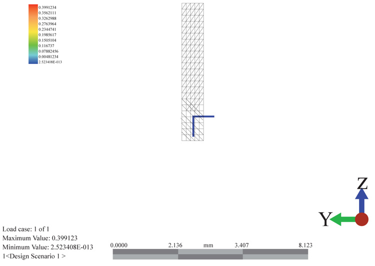
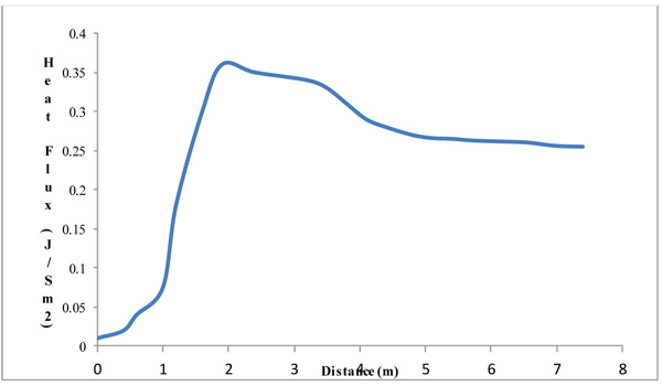
3.4.3.2. Heat Flux
The heat flux as observed in Figs. (14 and 15), increases above the inlet flue gas and remains constant throughout the height. It shows that the column experiences an adiabatic state only having its temperature increased with constant heat. A gradual increase and then decrease in the heat flux displays. From the graph, there is a sharp increase in the heat flux as it reaches the peak period and then reduces. The reduction tries to steady itself giving an adiabatic heat flow at the column. The little variation and changes is a factor of the tray pressure drops.
| Products | Volumetric Flow Rate | Tray Position | Temperature (oC) | ASTM (oC) |
|---|---|---|---|---|
| Off Gas | 369.97 | 1 | 46.29 | 0-30 |
| Light Naphtha | 3.890 | 1 | 46.29 | 30-100 |
| Heavy Naphtha | 1.507 | 2 | 76.53 | 80-200 |
| Kerosene | 730.13 | 16 | 139.13 | 170-280 |
| Diesel | 812.49 | 24 | 273.67 | 220-320 |
| AGO | 170.16 | 30 | 340.02 | 290-350 |
| Fuel Oil | 590.65 | 31 | 297 | - |
| Lube Oil | 190.97 | 31 | 374 | 350-575 |
| LTGO | 150.07 | 32 | 399.8 | 345-565 |
| HTGO | 0.000000539 | 36 | 419 | |
| Paraffin | 0.0000150 | 41 | 422.2 | >370 |
| Residue | 0.0000152 | 44 | 427.7 | 565-580 |
| Asphalt | 377.14 | 46 | 482.1 | >580 |
3.5. Separating Membrane
The rectifying section as well as the stripping section is being separated by a slim sheet of stainless steel as shown in Fig. (16) below. Stainless steel is known for its high thermal rigidity and resistivity to corrosion. Due to this reason, the stainless steel was selected as the separate medium as it can withstand the temperature and heat fluxes around it. They also seem to be more economically viable once service life and life cycle cost are considered. The solid work simulation software (FEA structural tool) was used to the temperature variation around it thereby confirmimg the viability of this approach.
3.6. HYSYS Simulation of the Integrated Distillation Column
The engine flue gas and the atmosphere residue both enter the column as described. This increases the temperature, vapor pressure and entropy of the atmosphere residue and then vaporizes the different components present in the atmospheric residue. This sub sequentially increases the temperature of the product cuts coming out of the column. The column consists of a 16 tray column which is to add up to the 31 trays at the rectifying section to make it a total of 46 trays.
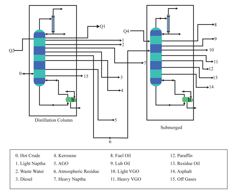
Fig. (17) shows a process flow diagram of the stripping and submerged combustion process via ASPEN HYSYS while Fig. (18) shows the simulation of the entire integrated distillation column using initial operating conditions (10000bpd design capacity, fixed temperature of 358.31oC and operating pressure of 700kpa of crude entering the main distillation column) that were used. The heat generated at the exhaust of the combustion burner served as re-boiler of another column since HYSYS does not have a submerged combustion burner in its package. Table 5 gives a summary view of the flow rate, temperature and the tray position of the products coming out from the integrated distillation column. It is observed that the paraffin, residue and asphalt record a lower boiling temperature than the ASTM standard. This is majorly due to the fact that at vacuum pressure, products are expected to boil out at a higher temperature when compared to the same product being distilled out from an atmospheric condition.
CONCLUSION
This study was able to design a 10,000bpd integrated distillation column that can refine bonny medium crude oil to simultaneously produce both standard atmospheric product and supposed Vacuum product all under atmospheric condition with the addition of a submerged combustion zone. The Integrated distillation column successfully brought out 369.97 ft3 ⁄hr., 3.890 ft3 ⁄hr., 1.507 ft3 ⁄hr., 730.13 ft3 ⁄hr., 812.49 ft3 ⁄hr., 170.16 ft3 ⁄hr., 590.65 ft3 ⁄hr., 190.97 ft3 ⁄hr., 150.07 ft3 ⁄hr., 0.000000539 ft3 ⁄hr., 0.0000150 ft3 ⁄hr., 0.0000152 ft3 ⁄hr. and 377.14 ft3 ⁄hr. of Off Gas, Light Naphtha Heavy Naphtha, Kerosene Diesel, AGO, Fuel Oil, Lube Oil, LTGO,HTGO, Paraffin, Residue and asphalt respectively. The Naphtha was successfully used as the source of fuel for the combustion flue gas where the Naphtha fuel comes into the engine at 110.3KPa, 25oC and 3.39ft3 ⁄ hr. The corresponding result of the flue gas from the engine leaves at 417.7 o C, 100.04KPa, 8.76 ft3 ⁄ hr and most importantly is the heat flow which is -2.1717 x 10⁵ Btu/hr (exothermic). Although HYSYS simulation software represents true-life scenario, Finite Element Analysis (FEA) tool determined both thermal and Computational Fluid Analysis (CFD) effect. It also helped to analyze any evidence of stress, strain, heat and other related engineering factors that could hinder productivity. This tool highlights the step by step impact on the distillation column and proved positive
CONSENT FOR PUBLICATION
Not applicable.
CONFLICT OF INTEREST
The authors declare no conflict of interest, financial or otherwise.
ACKNOWLEDGEMENTS
I want to express my deep thanks to the management of Covenant University, Nigeria for providing an enabling environment for this research. I also want to express my profound gratitude to my co-authors for their wonderful contributions