All published articles of this journal are available on ScienceDirect.
Better Heat and Power Integration of an Existing Gas-Oil Plant in Egypt Through Revamping the Design and Organic Rankine Cycle
Abstract
Objective:
The current study aims mainly to Maximize Condensate Recovery (NGLs), focusing on a gas processing train of Gas-Oil Separation Plant (GOSP) located in Egypt with a capacity of 4,230 kmole/h.
Methods:
The research study accounts for the constraint of Reid Vapor Pressure (RVP) specification, which makes the storage in floating roof tanks is of a great risk. The study proposes the installation of the cryogenic train that recovers condensates (C4+). This train comprises of compression unit, expansion unit, three-phase separators and a re-boiled absorber. The problem of RVP will no longer exist because of the re-boiled absorber achieving RVP according to export specifications (RVP below 82.74 kPa). Heat integration is applied over the whole process to minimize the reliability of the external utilities. Further, an Organic Rankine cycle (ORC) is introduced to the existing unit for more heat integration to develop useful work from process waste heat. Furthermore, both environmental emissions of CO2 and economic implications are investigated.
Results:
Energy integration played a vital role in decreasing the compressing power by about 31%, the cooling load by about 81%, and eliminating the heating load leading to zero CO2 emissions.
Conclusion:
The new energy-integrated retrofit scenarios exceed the recommended revamping schemes by previous works and base case in all aspects of condensate recovery, energy-saving, environmental concerning and economics.
1. INTRODUCTION
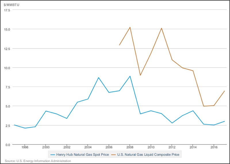
Natural gas is considered the cleanest among all fossil fuels with high calorific value and low percentages of impurities. It can be used for industrial and domestic applications as well as power generation plants, either steam or gas power plants. Raw natural gas, primary conditioned, has low cost so it is favorable fuel but not profitable as a commodity, so further treatment and processing should be applied to gain more valuable profit from natural gas. The typical composition of natural gas includes methane, ethane, propane, butanes, pentane and traces of heavier components. All the aforementioned components except methane are called hydrocarbon liquids. These hydrocarbon liquids should be removed from the natural gas not only to meet the assigned specifications to be transmitted safely to the consumers, but their commercial benefit is the major motive to recover them in a greater extent than required for transmission specifications. The hydrocarbon liquids can be divided into two groups: the first group is referred to as natural gas liquids (NGLs) which involve ethane, the desirable component for ethylene production and other petrochemical industries. Propane and butanes are valued as liquid fuel, Liquid Petroleum Gas (LPG), for residential uses or as feedstocks for petrochemical industries. The second group is the natural gas condensate which includes pentane and heavier constituents (C5+) [1]. The condensate is a stable liquid product at standard conditions of pressure and temperature. Moreover, it’s well-known with high API degree because of its light density and high volatility, which results in a valuable product with a premium price over raw natural gas and conventional petroleum crude as well. Fig. (1) shows that the prices of natural gas liquids are ranging from twice to five times of the natural gas prices, which emphasizes the economic importance of hydrocarbon liquids recovery. Hydrocarbon liquids recovery from natural gas can be accomplished by several techniques, depending on the desired degree of liquid recovery, ranging from simple dew point controlling to the complicated technologies that can achieve high ethane recovery. Early in the 20th century, NGLs recovery processes involved gas compression and cooling accompanied by condensate stabilization. In 1920s, the lean oil absorption technique was introduced to enhance the liquid recovery rich in butanes. Later in 1950s, refrigerated lean oil absorption technique was developed to recover lighter components. The process gas can be refrigerated by different techniques: mechanical refrigeration, expansion through J-T valve, or expansion through turboexpander [2]. NGLs recovery processes with turboexpander are usually recommended because of their high liquid recovery performance [3]. Egypt is on its way to being one of the leading countries in the petroleum refining and petrochemical industries. Natural Gas Liquids (NGLs) are considered the main feedstock for both industries. Egypt experiences a deficiency of NGLs, so it is more profitable to recover NGLs from characteristic gas.
This research is providing a new energy-integrated retrofit for an existing Gas-Oil separation plant in Egypt that was proposed to maximize condensate production. The adopted proposed technique can be considered as surface-enhanced oil recovery from produced gas. The energy-integrated retrofit will be confirmed by its economic feasibility to be conducted to contribute to solving this issue by modification of Gas-Oil Separation Plant (GOSP) located in Egypt to produce the NGLs by following a techno-economic revamping scheme with an energy-saving scope.
2. METHODOLOGY
Based on the HYSYS 8.8 model of the Gas-Oil Separation Plant (GOSP) of an existing Petroleum Company, which is simulated and verified with the actual data in previous work [5]. A new heat-integrated retrofit is proposed to achieve the maximum recovery of stable condensate (i.e., its Reid vapor pressure (RVP) does not exceed 82.74 kPa). The proposed retrofit is considered a kind of modification in the Gas Subcooled Process (GSP) [6]. The second objective of this research concerns energy savings, which can be achieved by applying pinch analysis for heat integration to determine the targets and design an appropriate heat exchanger network that satisfy the heating and cooling demands. An organic Rankine cycle is introduced as another approach to waste heat recovery and power generation. After environmental and economic evaluations are investigated to determine the carbon dioxide emissions and the profitability of this modification. Finally, results are summarized and compared with their corresponding from the base case and the recommended revamping scheme in previous studies [5].
3. METHODS AND TECHNIQUES
3.1. Retrofit Proposal
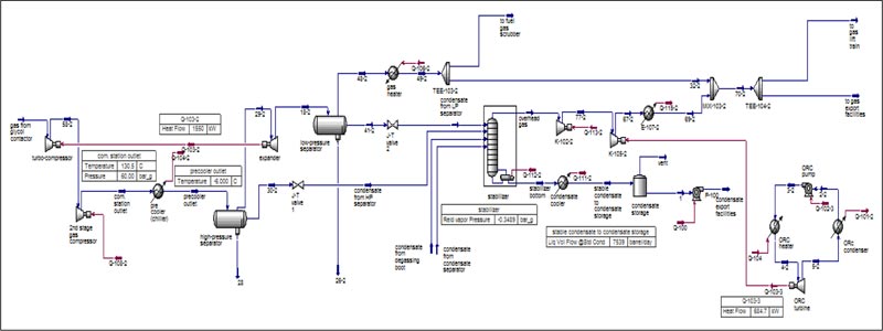
The full process flow diagram of the proposed modification includes three main sections: first, the cryogenic section aiming for NGLS extraction from the natural gas by creating a temperature drop below the gas dew point. This section involves a compression station to raise the gas pressure, a precooler to decrease the temperature of the high-pressure gas. The gas and condensed heavies are headed to the high-pressure separator to knock out the condensate formed and is then directed to the next section before the gas enters the turboexpander, which is the heart of the cryogenic process, to decrease the pressure of the gas back to the initial pressure accompanied by a further decrease in temperature which causes more condensate to be produced. After that, the mixture enters a low-pressure separator to collect the liquid hydrocarbon which is directed to the next section. The traces of water-glycol solution entrained in the natural gas feed are separated from the high-pressure and low-pressure separators and pumped to the glycol regeneration package.
The second section is the stabilization unit which mainly consists of a re-boiled absorber, stabilizer, attached to a compression train to raise the pressure of the overhead gas to be mixed with the main gas stream. The stabilizer is fed with four condensate streams of the same pressure of 301.3 kPa but differs in temperature. It has ten stages with the coldest stream, condensate from the low-pressure separator, in the top; the second stream, condensate from the high-pressure separator, is fed on the third stage followed by the third stream from the condensate separator, which enters on the fourth stage and finally the warmest stream, condensate from the degassing boot, enters on the sixth stage. The purpose of the multi-feed system is to enhance the stripping and mass transfer process inside the stabilizer to increase the separation efficiency; hence more barrels of stable condensate are produced from the bottom and are then cooled and pumped to the storage area.
3.2. Retrofit Simulation and Optimization
The HYSYS (Academic License) model, which simulates the retrofitting process, is recommending the Peng-Robinson equation of state as a fluid package since all components are almost hydrocarbons. Two gas streams from glycol contactors are mixed to flow as the feed stream of the proposed retrofit with tabulated conditions and composition, as illustrated in Table 1. Some simulation limitations were considered during the retrofitting process to construct a realistic and reliable model. These considerations, shown in Table 2, were selected according to the available operating conditions and the literature recommendations for the main equipment involved [7]. Three key parameters are controlling the condensate production from the proposed modification: the compression station outlet pressure, the precooler outlet temperature, and the Reid vapor pressure (RVP) of the stabilizer bottom product. Case studies were performed to determine the optimum value of the three main controlling parameters.
3.3. Energy Integration
Energy integration is introduced in the proposed retrofit in various techniques: first, as a site utility integration since the power produced by the turboexpander is used to drive the first stage compressor. Furthermore, the combined heat and power (CHP) technique is introduced by involving an Organic Rankine cycle into the proposed modification for the recovery of low-grade waste heat and power generation simultaneously [8]. Another way is heat integration, where pinch analysis technique is applied using Aspen Energy Analyzer software to plot the composite curves and determine the targets for minimum temperature difference (ΔTmin) equals 10 oC after proper data extraction, then heat exchangers network is designed to satisfy the required targets [9].
| Stream Conditions | |||||
|---|---|---|---|---|---|
| Temperature [oC] | 21.94 | ||||
| Pressure [kPa] | 1,725 | ||||
| Molar Flow [kmole/h] | 4,230 | ||||
| Stream composition | |||||
| Component | Mole fraction | Component | Mole fraction | Component | Mole fraction |
| Methane | 0.81068 | n-C12 | 2.63E-07 | n-C25 | 2.086E-13 |
| Ethane | 0.09698 | n-C13 | 6.95E-08 | n-C26 | 7.42E-14 |
| Propane | 0.05074 | n-C14 | 1.57E-08 | n-C27 | 0 |
| n-Butane | 0.01533 | n-C15 | 5.92E-09 | n-C28 | 0 |
| i-Butane | 0.00775 | n-C16 | 1.83E-09 | n-C29 | 0 |
| n-Pentane | 0.00380 | n-C17 | 1.46E-09 | n-C30 | 0 |
| i-Pentane | 0.00461 | n-C18 | 4.75E-10 | Benzene | 6.41E-05 |
| n-Hexane | 0.00253 | n-C19 | 1.97E-10 | Toluene | 6.84E-05 |
| n-Heptane | 0.00062 | n-C20 | 3.68E-11 | m-Xylene | 1.26E-05 |
| n-Octane | 0.00020 | n-C21 | 7.94E-12 | o-Xylene | 7.99E-06 |
| n-Nonane | 2.44E-05 | n-C22 | 3.84E-12 | p-Xylene | 6.64E-06 |
| n-Decane | 7.96E-06 | n-C23 | 1.25E-12 | Nitrogen | 0.0045 |
| n-C11 | 1.167E-06 | n-C24 | 4.83E-13 | CO2 | 0.0021 |
| Equipments | Simulation Limitations |
|---|---|
| Compressors | ▪ Outlet temperature less than 150 oC. ▪ The pressure ratio does not exceed 4.4. ▪ Adiabatic efficiency equals 75%. |
| Coolers and heat exchangers | ▪ The pressure drop from 30 kPa to 150 kPa. ▪ Air cooler outlet temperature higher than 35 oC. |
| Turboexpander | ▪ Outlet pressure of 1,731 kPa, feed stream pressure. ▪ Adiabatic efficiency equals 75%. |
| Stabilizer | ▪ Operating pressure near atmospheric pressure. |
| Organic Rankine cycle | ▪ Turbine feed temperature is 10 oC lower than the maximum operating temperature. ▪ Condenser pressure near atmospheric. ▪ Iso-pentane is used as a working medium. |
3.4. Environmental Evaluation
The environmental assessment is represented as CO2 emissions (kg/s) with equivalence to fuel burnt, QFuel (kW), in the operating fired heaters, which is calculated from (1), where α (=3.67) is the ratio of molar masses of CO2 and C, while NHV (kJ/kg) represents the net heating value of a fuel, equals 51600 kJ/kg for natural gas, with a carbon content of C% (75.4 for natural gas) [10].
 |
(1) |
3.5. Economic Analysis
Preliminary economic evaluation is conducted on the proposed integrated retrofit using the factorial method, developed by Lang [11-13], to determine its profitability. A rough estimation of the fixed cost, working cost and production cost of the proposed modification is evaluated depending on the estimation of the purchase cost of the main equipment using CAPCOST software [12] escalated to the year 2016 [13-16]. The net profit and pay-back time are calculated and compared to the previous work estimated by Elsheemy et al. [5, 17-20].
4. RESULTS AND DISCUSSION
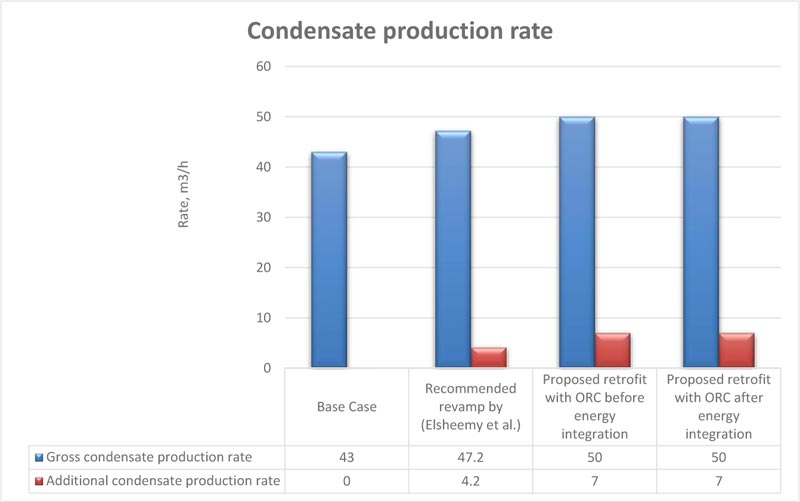
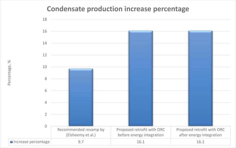
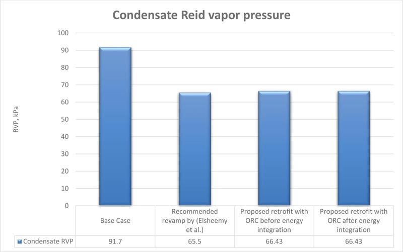
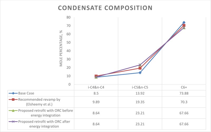
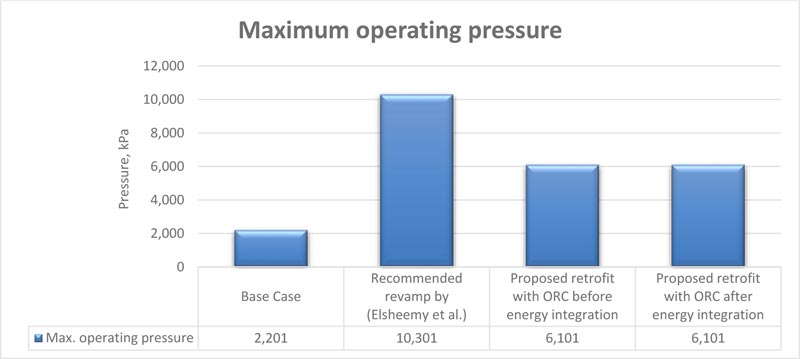
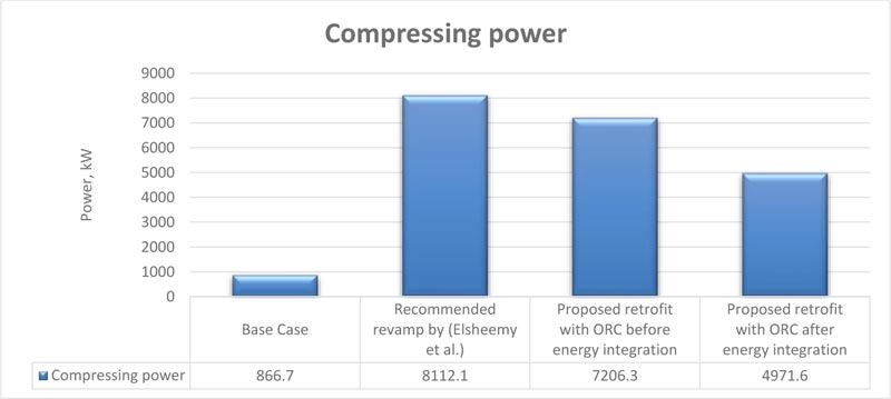
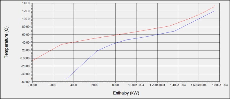
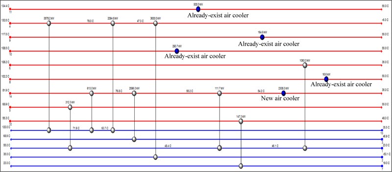
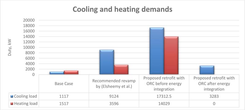
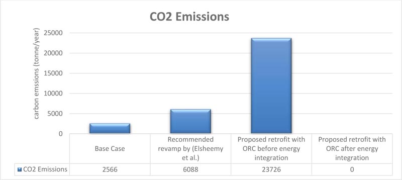
From the HYSYS 8.8 Model of the proposed retrofit, shown in figure 2 based on the simulation rules of thumb, it was found that the flow rate of stabilized condensate is directly proportional to the outlet pressure of the compression station reaching the plateau near 6,101 kPa. On the other hand, it decreases dramatically with precooler outlet temperature above -6 oC. regarding the RVP of the stabilized condensate, it was found that the critical RVP is about 66.43 kPa at which maximum stabilized condensate production occurs. Figs. (3-6) show that the proposed retrofit, before and after energy integration, achieves the same results in the condensate recovery aspect since it can achieve about a thousand additional barrels per day of stabilized condensate, RVP equals 66.43 kPa, richer in pentanes. As shown in Fig. (7), the energy-integrated model is operating at a moderate pressure of 6,101 kPa with the least compressing power, as shown in Fig. (8), because of utilizing of the generated power from the turboexpander and organic Rankine cycle. As shown in Fig. (9), there is no pinch temperature at the specified ΔTmin, the heating duty can be totally eliminated while the required cooling duty can be reduced to about 3300 kW. The designed Heat Exchangers Network (HEN), which satisfies the targets, is shown in Fig. (10). It was designed to make use of the already-existing air coolers to minimize the tie-ins and complex piping. From Fig. (11), it can be noticed that the designed Heat Exchangers Network (HEN) exhibits a great role in energy saving by reducing the cooling demand by about 14 MW and omit the heating load. Fig. (12) illustrates the direct relation between the heating demand and the amount of carbon dioxide emissions; therefore the energy-integrated model approaches to zero carbon emissions from heating operations. On the other hand, as shown in Table 3, it is considered the least in each cost and the highest profit among the others and reaches the break-even point in less than a year which is favorable in the oil and gas industry.
| Parameters | Recommended Revamp by (Elsheemy et al.) |
Proposed Retrofit Before Energy Integration | Proposed Retrofit After Energy Integration |
|---|---|---|---|
| Equipment cost [Million US$] |
8.06 | 8.77 | 6.56 |
| Total capital cost [Million US$] |
29.8 | 32.4 | 24.25 |
| Annual production cost [Million US$] | 7.66 | 9.8 | 4.25 |
| Additional condensate annual production [m3/y] |
33264 | 60567 | 60567 |
| Additional annual revenue [Million US$] |
16.74 | 30.46 | 30.46 |
| Annual net profit [Million US$] |
9.08 | 21.8 | 26.21 |
| Pay-back time [year] |
3.28 | 1.49 | 0.93 |
CONCLUSION
A new energy-integrated retrofit for an existing Gas-Oil separation plant in Egypt was proposed to maximize condensate production by achieving more than one thousand additional barrels per day of stabilized condensate, which corresponds to a 16.1% increase in percentage, with RVP equals to 66.43 kPa. This proposed technique can be considered as surface-enhanced oil recovery from produced gas. Energy integration played a vital role in decreasing the compressing power by about 31%, the cooling load by about 81%, and totally eliminating the heating load leading to zero CO2 emissions. The energy-integrated retrofit confirmed its economic feasibility by achieving an annual net profit of about 26.2 million dollars and a pay-back period of one year. To sum up, the new energy-integrated retrofit scenarios exceed the recommended revamping schemes by previous works and base case in all aspects of condensate recovery, energy-saving, environmental concerning and economics.
CONSENT FOR PUBLICATION
Not applicable.
AVAILABILITY OF DATA AND MATERIALS
Not applicable.
FUNDING
None.
CONFLICT OF INTEREST
Dr. Hany A. Elazab is the Editorial Board Member of The Open Chemical Engineering Journal.
ACKNOWLEDGEMENTS
Declared none.

