All published articles of this journal are available on ScienceDirect.
Potential Evaluation of PVDF/PAN Membranes for Separation of Oil from Industrial Waste
Abstract
Aim:
The aim of the experiment is to characterize the Modified Membrane from PVDF/PAN and its application in removing the Emulsified oil waste from the Industry.
Objective:
To get the maximum separation of the emulsified oil from the waste water, composite (PVDF/PAN) membrane was prepared in the laboratory.
Methods:
New PVDF/PAN blend based ultrafiltration membranes were synthesized by phase inversion method. The blend membrane was treated at room temperature with aqueous sodium hydroxide solutions.
Results:
The facile eco-friendly preparation of PVDF/PAN blended membrane has a wide potential for practical applications in emulsified wastewater remediation. The chemical functionality of the modified membranes was confirmed by IR spectra.
Conclusion:
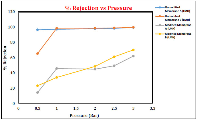
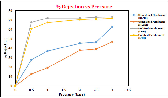
For the separation of emulsified oily wastewater, the as-prepared composite (PVDF/PAN) membrane could effectively separate oil/ water emulsions with separation efficiency of above 99.8%. Unmodified membranes (A and B) showed 95.4-99.8% rejection. However, in the case of membranes C and D, oil rejection was higher for the modified membranes as compared to the unmodified membranes.
1. INTRODUCTION
With the increasing development of petrochemical industries, a huge amount of oily wastewater has been produced from oil spilling or unavoidable emission, causing major harm to the ecosystem and human health [1-4]. Traditional separation methods like oil skimmers, centrifugation, adsorption and coalesces have been applied for oily wastewater purification [5-7]. However, most of the processes are high cost and low efficiency to separate oil/water mixture with oil droplet size less than 20 µm size [8]. Thus, literature survey regards as membrane separation process as an attractive separation technology due to low energy consumption, environmentally friendly, high separation efficiency, etc [9-12]. Microfiltration (MF), Ultrafiltration (UF), Nanofiltration (NF) and Reverse Osmosis (RO) are well-known pressure-driven membrane processes. Ultrafiltration membrane separation processes are recent tread technique accepted worldwide with no requirement of chemical reagents for the treatment, no oil content in filtrate water, compact and fully automated system. Various polymeric materials such as Cellulose Acetate (CA) [13], Polyacrylonitrile (PAN) [14], Polyvinylidene Fluoride (PVDF) [15, 16], Polyethersulfone (PES) [17], Poly(pphenylene sulfide) (PPS) [18] and Polysulfone (PSF) [19] have been widely used to prepare membranes for oil/water emulsion separations. Owing to high mechanical strength, good chemical stability and toughness, PVDF and PAN have been recognized as one of the suitable choices for the separation of oil/water emulsions [20-25]. This article focuses on preparation of PVDF/PAN blend ultrafiltration membranes of different compositions according to phase inversion process with alkali solution modification at room temperature. Characterization of the membranes by contact angle measurement, Attenuated Total Reflectance Infra-red (ATR-IR) and atomic force microscope (AFM) were performed and measurement of the pure water flux (PWF) at different operating pressures and % rejection of emulsion wastewater were also studied.
2. METHODS
2.1. Materials & Chemicals
Polyvinylidene fluoride (PVDF) and Polyacrylonitrile (PAN) powder was purchased from Solvay Solexis, France and Aldrich Chemicals (USA), respectively. Solvent N-methyl-2-pyrrolidinone (NMP - 98%) and Acetone (99%) were purchased from Spectrochem Pvt Ltd, India and Ranbaxy fine chemicals ltd, New Delhi, India, respectively. Sodium Hydroxide (NaOH – 99.9%) powder was purchased from Ranbaxy fine chemicals ltd, New Delhi, India. For the experimental analysis, hydraulic oil was purchased from Servo Hydraulic oil centre (IOCL), Bandra (EAST), Mumbai, India.
2.2. Membrane Casting Process
Ultrafiltration membranes were prepared from NMP solution of PVDF and PAN blends on a non-woven polyester fabric (H 2564) according to phase inversion method using motor driven continuous prototype membrane casting machine as shown schematically in Fig. (1) (Schematic diagram). The freshly casted polymer film on the fabric supports was gelled at 21- 25 ◦C in water bath containing deionized water [26, 27]. Casting thickness of membranes was fixed at 160 μm by using micrometers attached to the casting blade. The relative humidity of the polymer chamber was maintained at around 58% using dehumidifier air. Casted membranes were allowed in gelation bath for an hour and then preserved in deionized water until testing. The thicknesses of the membranes were measured with micrometer at different places. The membranes were characterized for pure water permeation rate and for the separation of oil-water emulsion.
2.3. Membrane Characterization
The morphology of prepared membranes was characterized by Attenuated Total Reflectance Infra-red (ATR-IR) (SICHART, VallabhVidyanagar, Anand, India) and Atomic force microscope (AFM) (SICHART, VallabhVidyanagar, Anand, India). Contact angles (CAs) of membrane were detected for chemical composition and surface hydrophilicity by a contact angle goniometer (CSM-CRI Laboratory, Bhavnagar, India). Systematic performance studies were conducted in different operating conditions such as variations in feed concentration, feed solution and Operating pressure.
2.4. Oil/Water Emulsions Preparation
The oil/water emulsion was prepared by taking organic solvent such as petroleum ether and toluene which was dispersed into deionized water by stirring for 60 min, and then the oil/ water emulsion was obtained. Besides, the surfactant-stabilized oil/water emulsions were also prepared. Firstly, surfactant-free emulsions including petroleum ether and toluene were prepared; then, 10 mg of Tween-80 as emulsifying agent was added into the above solutions by stirring for 12 h. All the surfactant-stabilized oil/water emulsions were stable for several months until there was no precipitation observed.
2.5. Separation Phenomena of Oil/Water Emulsion
The permino experimental setup (NF/UF/RO) supplied by perminonics membrane private limited, Vadodara, India is shown in Fig. (2). It consists of a flat sheet module inbuilt as well as a hollow fibre and tubular module. The test cell, made of stainless steel (dimension: 200 x 100 x 40 mm3) and inner dimension of the test cell was 150 mm x 100 mm x 2 mm. Stainless steel gauge of 250 mesh size was kept on which 1 mm stainless steel plate was profound. The whole membrane assemble was covered with filter paper and blended prepared membrane was installed. Strength in terms of mechanical operation can be enriched using such installation of membrane material. Variable frequency drive (VFD) to control the feed flow, pressure gauge (both inlet and outlet stream) and high pressure switch (HPS) having trip shut down limit kept as 15 kg/cm2 (Maximum limit of pressure is 40 kg/cm2) as safety point are the major parts to the set-up. Emulsified oil/water Feed solution from the feed tank (5 litre maximum capacity) was pressurized by high pressure pump and allowed to flow into the test cell. Reject stream from the membrane assembly was collected back and recycled to the feed tank using rotameter. After each filtration, the blend membrane was washed with ethanol and deionized water. The flux of membranes is calculated by the following equation:

(1. Fabric supply roller, 2.Guiding rollers, 3.Polymer solution, 4.Water gelation Bath, 5. Membrane Winding).
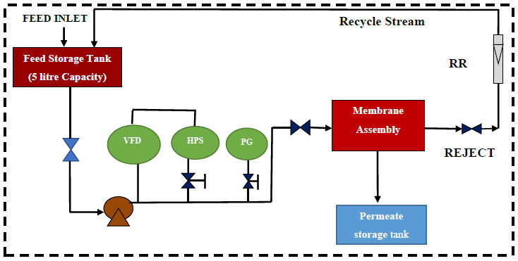
VFD: Variable Frequency Device; HPS: High Pressure Switch, Shut down pressure in case of emergency is 15 kg/cm2; PG: Pressure Gauge; RR: Reject Rotameter.


Where, where V (L) is the volume of permeate flow, A (m2) is the effective area of filter, t (h) is the filtration time. The separation efficiency (R %) of membranes was evaluated by measuring the total organic carbon of oil/water emulsion.
The flux recovery rate (FRR) of membranes is calculated by the following equation:
Where, Jw0 is the pure water flux before filter oil/ water emulsion, Jwt is the pure water flux after oil/ water emulsion separation experiment.
3. RESULTS AND DISCUSSION
3.1. Membrane Preparation & Modification
Polyvinylidene fluoride (PVDF) – polyacrylonitrile (PAN) blends membrane of different composition was prepared in N-methyl-2-pyrrolidone (NMP) solution according to phase inversion method. Water containing 0.1% SLS was used as the gelation medium. The preparation conditions and the characteristics of the membranes are presented in Tables 1 and 2. The amount of PVDF, PAN and PVP was varied from 10 to 14%, 2 to 4% and 2%, respectively while keeping the total amount (PVDF + PAN + PVP) polymers as 16 to 20%. Modification of blend membranes was performed by treating 2% aqueous alkaline solution (NaOH) for 2 hours at room temperature. Depending on the reaction chemistry that occur between nitrile (-CN) groups and sodium hydroxide, 16, 18 and 20% modified membranes were prepared. Solubility of NaOH treated PVDF/PAN blend was tested in polar aprotic solvents. It was observed that the PVDF/PAN blend membrane treated with less than 0.5N NaOH was soluble in NMP and other aprotic solvents while PVDF/PAN treated with 0.5N and higher concentration of NaOH was insoluble in NMP in which it was freely soluble before the treatment. This clearly indicates the formation of hydrophilic functional groups like –COOH and –CONH2, which resist the dissolution of modified PVDF/PAN blend membrane in an aprotic solvent.
3.2. Membrane Pure Water Flux
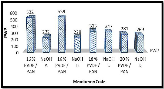
Pure Water Flux (PWF) is a preliminary parameter for the UF membranes. Generally, PWF is strongly dependent on membrane morphology such as thickness of the membrane, Pore Size Distribution (PSD) and porosity of the top skin layer, which in turn reflects the effects of membrane preparation conditions like casting dope composition (concentration of the polymer, types of additives, solvents), as-cast thickness, gelation medium, etc. The Pure Water Fluxes (PWF) of membranes exponentially decrease with an increase in the polymer composition in casting solution when total polymer composition was 16%, 18% & 20%. The PWF was decreased on increasing the polymer (PVDF+PAN) concentration from 16 to 20% in the dope solution in NMP which clearly reveals the influence on pore size and porosity of the membrane by polymer content. The effect of different membranes prepared with code v/s pure water permeability is indicated in Fig. (3).
3.3. Morphology Study of PVDF/PAN Blend Membrane
3.3.1. Surface Hydrophilicity
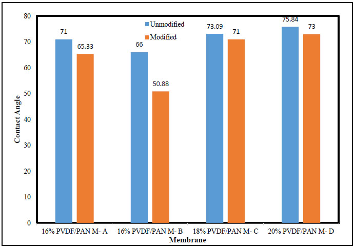
Generally, relative hydrophilicity of surface can be qualitatively determined by measuring contact angle of water droplets. The contact angle measurement of the membranes determined by the instrument shown in Fig. (4). The hydrophilic nature of membranes surface increases with % PAN increase in polymer solution. However, contact angles of the membranes prepared using 18% & 20% total polymer solution are comparatively higher than those of the membranes made of 16% total polymer, for the same concentration of PVP. Thus, contact angle values depend on surface chemistry, porosity and surface roughness and heterogeneity. The lower contact angle for membrane A & B is due to PVP impregnation at the top layer of the casting solution layer during membrane formation (before entering into the gelation bath). This results in the formation of a very thin skin layer of PVP along with PVDF-PAN blend support. Since PVP is soluble in water, it leaches out during phase inversion process and thus creates a membrane with higher porosity and higher roughness. The increase in surface porosity and roughness usually causes a decrease in the contact angle of the membrane surface. This clearly indicates that the NaOH treatment imparts hydrophilic characteristics to the membrane surface due to the formation of the carboxylic acid group and amide functional groups. The structure of modified and unmodified membranes was confirmed by IR spectra. Results showing some new peaks at 1743 and 1662 cm-1, which are apparently assigned to carbonyl stretching of carboxylic acid and amide group respectively, due to the arise of hydrolysis of nitrile (CN) group during treatment with NaOH solution.
| Membrane Code | % PVDF | % PAN | % PVP | % NMP |
Total Polymer Concentration |
|---|---|---|---|---|---|
| Membrane A | 10 | 4 | 2 | 84 | 16 |
| Membrane B | 12 | 2 | 2 | 84 | 16 |
| Membrane C | 14 | 2 | 2 | 82 | 18 |
| Membrane D | 14 | 4 | 2 | 80 | 20 |
| Membrane Code | Thickness (μm) | PWP (LMH) |
|---|---|---|
| Membrane A | 250 | 532 |
| Membrane B | 270 | 539 |
| Membrane C | 220 | 325 |
| Membrane D | 240 | 281 |
| NaOH A | 260 | 232 |
| NaOH B | 280 | 228 |
| NaOH C | 240 | 317 |
| NaOH D | 260 | 269 |
3.3.2. Attenuated Total Reflectance Infra-red (ATR-IR)
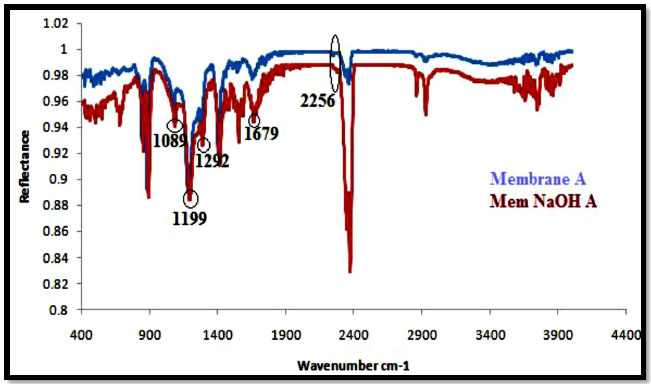
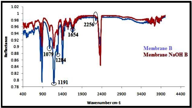
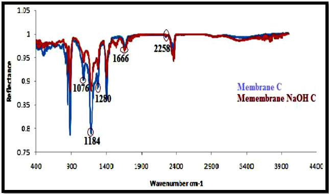
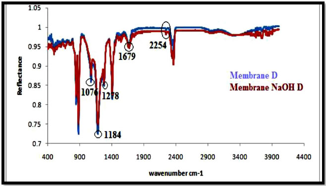
The ATR-IR spectra of PAN/PVDF blend membranes before and after hydrolysis of sodium hydroxide (NaOH) are shown in Figs. (5-8). The nature of the functional groups present on the top surface of membranes was identified by Attenuated Total Reflectance infra-red (ATR-IR) spectroscopic technique. PVDF showed peaks at 1000-1400 cm-1 and PAN showed peaks at 2240-2260 cm-1. The bands for modified membranes occurred at 1300-1800 cm-1 due to hydrolysis. Figs. (5 and 6) show that the FT-IR subtraction spectra of the substances on the membrane surface before and after hydrolysis of the 16% PAN/PVDF blends ultrafiltration membrane. In the spectra, the peaks at 2256 cm-1 were attributed to absorption by nitrile groups, which is the characteristic absorption of PAN. The bands near 1089 cm-1, 1199 cm-1 and 1292 cm-1are assigned to –CF2 groups in PVDF. Figs. (7 and 8) show the ATR-IR subtraction spectra of the substances on the membrane surface before and after hydrolysis of the 18% and 20% PAN/PVDF blends ultrafiltration membrane, respectively. In the spectra, the peaks at 2258 cm-1 were attributed to the absorption by nitrile groups, which is the characteristics absorption of PAN and appears in each spectrum. The bands near 1076 cm-1, 1184 cm-1 and 1280 cm-1are assigned to the –CF2 groups in PVDF.
3.3.3. Atomic Force Microscopy (AFM)
Figs. (9 and 10) show the AFM images of the blend membranes with sodium hydroxide (NaOH). Membrane surface morphology can be studied by measuring the surface roughness using high-resolution windows based NT –MDT surface analysis software, as shown in Table 3. It reports different structural sizes on the membrane surface and clearly indicates that the membrane average surface roughness was affected by alkali treatment. On the basis of the value of average roughness (Ra), we concluded that the roughness of the membrane surfaces increased with increasing NaOH contents. On the one hand, this resulted from the aggregation of NaOH particles on the membrane surface, and on the other hand, the craters on the membrane surface help to increase the roughness of the membrane. However, we expected that the surface of membranes could be as smooth as possible to achieve good hydrophilicity. In addition, the hybrid membrane exhibited a slightly higher roughness, but the hydrophilicity of membranes was enhanced by the presence of NaOH. Alkali treatment causes the hydrolysis of the hydrophobic nitrile group to a more hydrophilic carboxylic group.
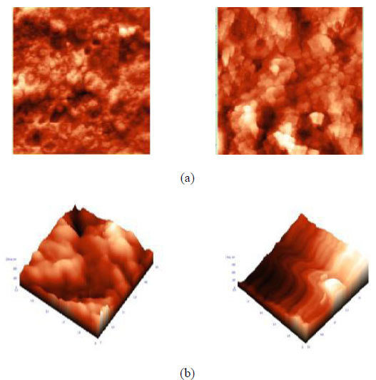
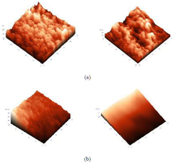
| Membranes | Average Roughness (Ra) |
|---|---|
| Membrane A | 22.00 |
| Membrane B | 13.30 |
| Membrane C | 20.46 |
| Membrane D | 30.80 |
| NaOH treated Mem-A | 32.84 |
| NaOH treated Mem –B | 29.90 |
| NaOH treated Mem-C | 21.12 |
| NaOH treated Mem-D | 26.32 |
3.4. Effect of Operating Pressure
3.4.1. Pure Water Flux Membrane A & B
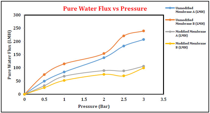
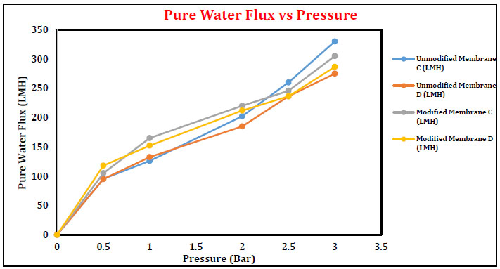
Pure water flux of membranes A and B as a function of operating pressure is plotted in Fig. (11). In general, pure water flux is directly proportional to the operating pressure. An increase in pure water flux was observed in the case of membranes A and B with the increased operation pressure in the range of 0-3 bar. Pure water flux obtained for membrane B is slightly higher than membrane A. After modification with sodium hydroxide, the PWF is decreased as compared to unmodified blend UF membrane. Immersing the membrane in alkali solution indicates the color changes. Light-yellowish to reddish-brown color appeared, which did not disappear during the entire period of alkali treatment. The appearance of reddish brown color confirmed the formation of cyclic –C=N– conjugated naphthyridine structures in the PAN, which was verified by UV, IR and ESR techniques. Analytically proved results suggested that some significant changes in the membrane porous structure have occurred while it is treated with alkali solution. Similar results for membranes C and D are depicted in Fig. (12).
3.4.2. Effect of Operating Pressure on Oil-in-Water Emulsion
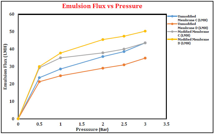
Major pollutants to the aquatic environment are the oil-water emulsion and hence, separation to be carried out only through tailor made membranes. Emulsion flux was increased with increase in pressure from 0 to 3 bars. Maximum flux value was obtained for unmodified membranes compared to modified membranes, which is similar to the trend in pure water flux. However, % oil rejection of unmodified membranes was lower than the modified membranes. Fig. (13) shows that the emulsion flux of unmodified and modified membranes was increased with increasing pressure at 0 to 3 bars. The flux at 3 bars pressure for membrane A and membrane B was found to be 192.42 LMH and 256.45 LMH, respectively. For the modified membranes, the fluxes were 116.42 LMH and 150.96 LMH for membranes A and B, respectively. Flux value was decreased with alkali treatment of the membranes and also witnessed the conversion of nitrile group to cyclic naphthyridine and amide.
3.4.3 % Rejection of Oil for Unmodified and Modified Membrane
The % rejection was increased for unmodified and modified membranes with the increase in applied pressure from 0 to 3 bars. Unmodified membranes have given maximum oil rejection compared to modified membrane A and membrane B. The data indicate that oil rejection was in the range of 95.4-99.8% for the unmodified membranes, whereas the oil rejection was 14-70% for the modified membranes. Further, the rejection also increased with an increase in applied pressure. This attributed to the fact that the increase in applied pressure causes a net increase in driving force and an increase in permeate flux without affecting the solute transport through the membrane. The net increase in water flux naturally results in the increase in solute rejection, as discussed in Figs. (14 and 15).
3.4.4. Fourier Transform Infrared Spectroscopy
The unmodified membrane structure is seen in Fig. (16) For the modified membrane, the changes in the structure of the membrane due to the effects of the NaOH are shown in Fig. (17). Table 4 indicates the intensity of light passing during the spectroscopy may be weak, medium or strong intensity representing the strength of the various bonds present. The unmodified membrane shows C-N vibrations of aromatic compounds and O-H bending and C-H stretching vibrations of tertiary alcohols and phenols. These disappear in the modified membrane sample. This is due to interactions with NaOH. Similarly, C-F stretching vibrations are also found to disappear in the modified membrane. The presence of C-H stretching due to alkane is seen for the modified membrane sample, which may have appeared due to reactions with the NaOH. Stretching vibrations of C-Cl halogen compounds are also seen in the modified membrane sample but were not present in the unmodified sample.
| Wave Number (cm-1) | Intensity | Assignment |
|---|---|---|
| 3439 | M | N-H Stretching vibrations, secondary free; one band in Amines. |
| 1585 | W | Unsaturated nitrogen compounds –N=N- stretching vibrations, azo compounds, Secondary N-H bending vibrations. |
| 1384 | S | Alkane, gem-dimethyl, Halogen compounds, C-F stretching vibrations |
| 1364 | S | Alkane, tert-butyl, Halogen compounds, C-F stretching vibrations |
| 1171, 1104 | S | Sulphur compounds C=S stretching vibrations |
| 606 | S | Halogen compounds, C-Cl stretching vibrations |
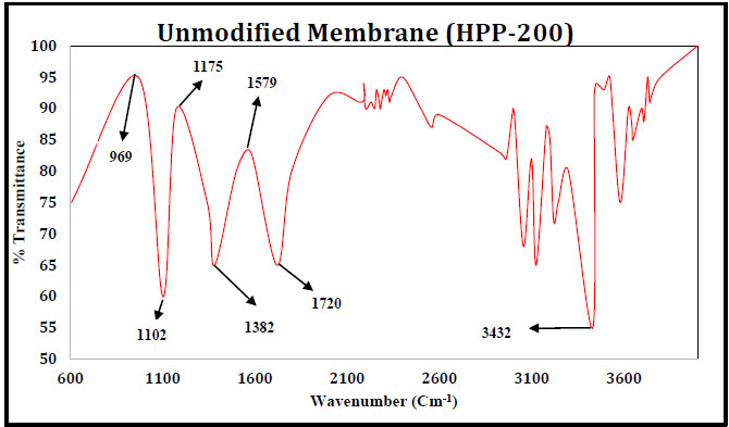
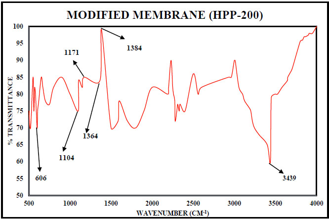
The stretching and vibrations are due to the interactions of the membrane with the NaOH in the feed. Though much change is not observed in the membrane properties, some variations in stretching and bending of certain bonds are observed which is the result of interactions of the solution components with the membrane.
CONCLUSION
New PVDF/PAN blend-based ultrafiltration membranes were synthesized by phase inversion method. The blend membrane was treated at room temperature with aqueous sodium hydroxide solutions. For separation of emulsified oily wastewater, the as-prepared composite (PVDF/PAN) membrane could effectively separate oil/ water emulsions with separation efficiency of above 99.8%. Unmodified membranes (A and B) showed 95.4-99.8% rejection. However, in the case of membranes C and D, oil rejection was higher for the modified membranes as compared to the unmodified membranes. These differences in the oil rejection strongly indicate that the oil rejection depends not only on the modification but also on the concentration of PVDF in the unmodified membrane. Oil rejection was increased with the increase in applied pressure. ATR-IR Spectra depicts the absorption of PVDF and PAN at band range 1000-1300 cm-1 and nearby 2250-2260 cm-1 on the modified membrane FTIR spectra confirm the C–C band and C-C-C asymmetric stretching vibration band of PVDF were observed at 1171 and 889 cm−1, respectively while PAN corresponds the characteristic absorption peaks of nitrile (–C N) group at around 2240 cm-1 and (CH2) group at 1390 cm-1. Therefore, the facile eco-friendly preparation of PVDF/PAN blended membrane has a potential for practical applications in emulsified wastewater remediation.
NOMENCLATURE
| PVDF | Polyvinylidene difluoride |
| PAN | Polyacrylonitrile |
| PVP | Polyvinylpyrrolidone |
| NMP | N-methyl-2-pyrrolidone |
| PEG | Polyethylene glycol |
| UF | Ultrafiltration |
| MF | Microfiltration |
| NF | Nanofiltration |
| RO | Reverse Osmosis |
CONSENT FOR PUBLICATION
Not applicable.
AVAILABILITY OF DATA AND MATERIALS
The authors confirm that the data supporting the findings of this study are available within the article.
FUNDING
This work was financially supported by Department of Chemical Engineering, P. P. Savani University as a part of in-house research work.
CONFLICT OF INTEREST
The authors declare no conflict of interest, financial or otherwise.
ACKNOWLEDGEMENTS
We are grateful to the P P Savani University management for providing the research facility of membrane casting unit as well as permino membrane set-up throughout the experiment.

