All published articles of this journal are available on ScienceDirect.

A Review on CO2 Absorption using Chemical Solvents at Low and High CO2 Partial Pressure Conditions in a Packed Column
Abstract
CO2 removal is important for industrial flue gas treatment, biogas enhancement, and natural gas (NG) processing applications. Chemical absorption using an amine-based solvent is a proven technology for CO2 removal from various gases. In recent years, various promising amine solvents have been investigated, either as single or blended solutions, to enhance the CO2 absorption process at low and high CO2 partial pressure conditions. Low CO2 partial pressures (1 – 47 kPa) have been utilized in numerous research works focusing on flue gas treatment and biogas enhancement applications. On the other hand, high CO2 partial pressures were instead applied in NG processing ranging between 750 and 1600 kPa. To provide more insight into the current trends, existing research on CO2 absorption in amine-based solvents is presented in this review focusing on absorption performance in a packed column at low and high CO2 partial pressures. Reports on the effect of different parameters, namely CO2 partial pressure, gas, and liquid flow rates, amine concentrations, and liquid temperature, on the removal of CO2 in the packed column are included. Based on the review, the future direction is further highlighted in this area.
1. INTRODUCTION
Carbon dioxide (CO2) exists as one of the contaminants in the industrial flue gas. Approximately 80% of the total greenhouse gas emissions are contributed by CO2, and, therefore, it acts as the main contributor to global warming and resultant climate changes [1]. Major industrial flue gas sources contribute to CO2 emissions from industrial activities, including coal-fired power plants and natural gas burning, cement industries, and petrochemical, iron, and steel refineries. CO2 emissions are mostly formed by the combustion of fossil fuels [2]. The CO2 contents in flue gas streams are generally between 3 to 15 vol.%, depending on the types of fossil fuels used [3]. The CO2 content in the flue gas of power plants powered by coal needs to be reduced to less than 1.5% of CO2 concentration, while NG power plants require a lower concentration of 0.5% CO2. Thus, CO2 capture technology plays an important role in removing CO2 contaminants before the treated flue gas can be released into the atmosphere.
Meanwhile, renewable energies, such as biogas, primarily consist of methane (CH4) (40–75 vol.%), with impurities, such as CO2 (15–60 vol.%) and trace gases of hydrogen (H2), ammonia (NH3), hydrogen sulfide (H2S), water vapor (H2O) and nitrogen (N2) [4, 5]. The compositions of biogas vary depending on the organic substrates used in the anaerobic digestion process for biogas production [6]. Biogas upgrading is one of the essential processes of removing unwanted impurities, resulting in methane-rich biogas with high calorific value [6, 7]. The utilization of methane-rich biogas is mainly for power generation and vehicle fuel in transportation, replacing fossil fuel as an energy resource [9, 10].
On the other hand, CO2 must be removed from raw natural gas (NG) at both onshore and offshore gas processing sites. Besides CO2, the composition of raw NG is mainly CH4, small portions of other hydrocarbons (C2H6, C3H8, and C4H10), and trace elements (N2, O2, and H2S). The heating values of NG are reduced with a higher CO2 presence in NG. Furthermore, CO2 can increase the possibility of corrosion in pipelines and processing equipment when moisture is present. Hence, CO2 removal is also an essential process to increase pipeline gas quality and achieve the required sales gas specifications for marketing purposes [11]. CO2 concentration must be decreased to less than 3% for pipeline sale gas specification, while the requirement for LNG feedstock is less than 50 ppm CO2.
The process criteria and requirements applied to the flue gas, biogas, and NG applications have significantly different degrees of CO2 removal, types of the feed gas, the design criteria of the process equipment, and the operating conditions. Table 1 compares the industrial flue gas treatment, biogas upgrading, and NG processing applications [12, 14].
A number of review articles comparing CO2 capture technologies in terms of process performance and the use of various types of solvents for the removal process have been published. However, limited journals have provided an up-to-date review on mass transfer performance for CO2 absorption into amine solutions in packed columns. Thus, this study presents the recent progress in CO2 capture using chemical absorption methods between high- and low-pressure conditions in a packed column. The advantage and disadvantages of the established CO2 capture technologies are also systematically reviewed. Data used in this study were collected from SCOPUS, a global database that provides access to reliable data in various research fields. It is an analytical tool used to analyze, track, and visualize research trends. The publications from 2012 to 2020 on the mass transfer performance in terms of overall volumetric mass transfer coefficient, KGav, for CO2 absorption in a packed column written in English were reviewed.
1.2. CO2 Capture Technologies
The conventional CO2 capture technologies mainly include the process of absorption, adsorption and cryogenic, and membrane separations. In Table 2, the challenges in CO2 capture technologies are summarized [14, 15].
| Criteria | Flue Gas Treatment | Biogas Upgrading | Natural Gas Processing |
|---|---|---|---|
| Purpose of CO2 removal | To reduce CO2 emissions into the atmosphere | To produce methane-rich gas with high calorific value as an alternative fuel resource |
To prevent corrosion in the gas pipelines and meet the requirement of pipeline gas quality and sales gas specifications |
| The concentration of CO2 in the feed gas | In general: 3 – 15% Power plant Coal-fired: 14% Natural gas turbine: 4% |
In general: 13 – 50% The feedstock used for the biogas production resulted in different biogas compositions |
Conventional gas: 1–10% CO2-rich gas: > 10% Mix gas offshore: 30–50% of CO2 |
| Gases present in the feed gas | CO2, N2, SO2, O2 | CH4, C2H6, C3H8, CO2, H2, N2, H2S, O2, H2O | CH4, C2H6, C3H8, C4H10, CO2, O2, N2, H2S |
| The pressure of feed gas | Atmospheric | Biogas can be collected and stored in a cylinder at various pressures. The critical pressure of biogas for liquefaction is 47.5 bar |
High pressure of up to 200 bar (offshore condition) |
| Purity of the treated gas |
Power plant Coal-fired: < 1.5% of CO2 Natural gas turbine: < 0.5% of CO2 |
Pipeline gas: < 3% CO2 |
Pipeline gas: < 3% of CO2 LNG feedstock: < 50 ppm CO2 |
| CO2 Capture Technologies | Advantages | Disadvantages |
Treated Gas (%) |
Methane Loss (%) |
|---|---|---|---|---|
| Absorption | • Applicable for capturing low concentration of CO2. • 95% recovery rate • Higher product purity |
• Absorbent loss • Degrades and corrodes equipment • Absorbent emission affects the environment. • Requires high absorber volume • High viscosity • High regeneration energy |
> 98 | 0.04–0.1 |
| Adsorption | • Low energy regeneration • Low CO2 recovery • Applicable for separating CO2 and H2S simultaneously |
• Difficulty in handling solid • Slow adsorption kinetics • Low CO2 selectivity • Regeneration leads to thermal, chemical, and mechanical instability |
96–98 | 1–3.5 |
| Membrane Separation |
• A regeneration process is not required. • Low energy consumption • Waste streams are not required. • Simple modular system |
• Plugged membranes by impurities in the gas stream • Low permeation selectivity of CO2 over other gases • Limitation on the operating temperature • Low CH4 purity |
90–96 | 0.5–20 |
| Cryogenic Separation |
• Performing well at high pressures • Economically feasible at high CO2 concentration • Low CH4 losses |
• High regeneration energy requirement • Pre-treatment required to avoid blockages and before distillation • High capital cost |
99 | 0.5–3 |
The highest CO2 removal efficiency was observed using cryogenic separation, which utilizes the process of cooling and condensation in separating CO2 from the gas stream. However, the intensive energy requirement for cooling is of concern because it can increase the operating cost [15]. Meanwhile, the lowest performance in the CO2 separation with the maximum removal of 96% was observed for membrane separation. The working principle of this technology uses a membrane as a permeable material [16] to separate CO2 molecules. However, low membrane selectivity is the major limitation of this technology because the separation between CH4 and CO2 depends on the permeability properties of the membranes. Consequently, low membrane selectivity and permeability limitation can decrease CH4 purity in treated gas. Besides, adsorption can also be performed by increasing the operating pressure, which would result in the gas being adsorbed and vice versa for the regeneration process. The performance of removing CO2 from the stream also showed a promising result in the range of 96% to 98%. However, this process is complex and requires extensive control [17].
CO2 capture can also be performed using physical and chemical absorptions. The working principle of physical scrubbing is applied based on Henry’s Law, which states that CO2 is more soluble than CH4 [18]. The absorption of CO2 is done at high pressure and low pressure. In contrast, the regeneration process is performed by heating, pressure reduction, or both. For instance, the operation of the absorption process at high CO2 partial pressures consequently leads to increased energy requirement for gas pressurization. In CO2 removal using chemical absorption, it should be noted that CO2 is more reactive than CH4, whereby CO2 reacts with the chemical solution in a counter-flow motion [10]. Based on the operating pressure, percentage of methane loss, and final purity of the treated gas, chemical absorption shows the best potential for removing CO2 and other impurities from the gas stream.
Recently, the focus of studies has turned to enhancing the CO2 capturing process by proposing a new or promising blended solvent. Studies were also conducted under different operating conditions, aiming to enhance the absorption performance. Until now, the number of research publications for the CO2 capturing field has been growing, which provides high-quality data required for further development and design of the CO2 absorption process. Table 3 shows the top-listed authors who contributed to the CO2 capture field from 2010 until now.
| Authors | Affiliation | Publications |
|---|---|---|
| Svendsen, Hallvard Fjøsne | Norges Teknisk-Naturvitenskapelige Universitet, Department of Chemical Engineering, Trondheim, Norway | 96 |
| Tontiwachwuthikul, P. Paitoon | Clean Energy Technologies Research Institute, Faculty of Engineering and Applied Science, Regina, Canada | 82 |
| Rochelle, Gary Thomas | The University of Texas, Austin, United States | 72 |
| Liang, Zhiwu | Hunan University, Joint International Center for CO2 Capture and Storage (iCCS), Changsha, China | 70 |
| Idem, Raphael O. | The University of Regina, Department of Industrial and Systems Engineering, Regina, Canada | 69 |
| Yu, Hai | CSIRO Energy, Mayfield, Australia | 60 |
| Gao, Hongxia | Hunan University, Department of Chemical Engineering, Changsha, China | 56 |
| Hanson, Ronald | Stanford University, Palo Alto, United States | 55 |
| Fang, Mengxiang | State Key Laboratory of Clean Energy Utilization, Hangzhou, China | 51 |
| Puxty, Graeme Douglas | CSIRO Energy, Newcastle, Australia | 49 |
| Mohd Shariff, Azmi | Universiti Teknologi PETRONAS, Seri Iskandar, Malaysia | 49 |
| Feron, Paul | CSIRO Energy, Newcastle, Australia | 47 |
| Knuutila, Hanna K. | Norges Teknisk-Naturvitenskapelige Universitet, Trondheim, Norway | 47 |
| Luo, Xiao | Hunan University, Provincial Hunan Key Laboratory for Cost-effective Utilization of Fossil Fuels Aimed at Reducing Carbon-dioxide Emissions, Changsha, China | 45 |
| Chen, Jian | Tsinghua University, Department of Chemical Engineering, Beijing, China | 43 |
Their research articles were mostly published in top academic journals. Across a timeline from 2010 until now, the International Journal of Greenhouse Gas Control is the first most popular source, with 516 research articles focusing on carbon capture and usage and storage (CCUS) technology specifically. The second most popular journal is Industrial and Engineering Chemistry Research, with 314 research articles. It is followed by the third most popular journal, Chemical Engineering Journal, with 246 research articles. The following section further reviews recent research on CO2 capture, focusing on chemical absorption at high and low operating conditions in packed columns.
1.3. Capturing CO2 using Chemical Absorption
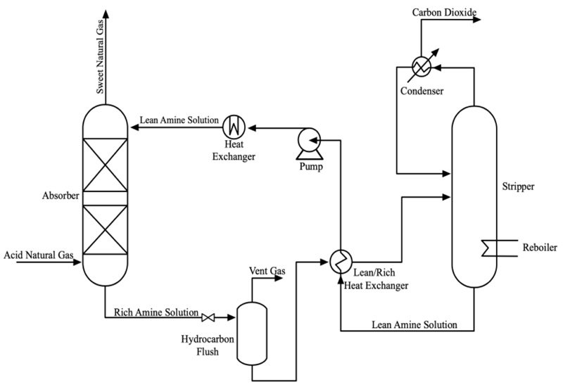
Chemical absorption is the preferred technology for capturing CO2 because this system effectively removes CO2 from the desired target. The gas-liquid contacting schemes used in industrial CO2 absorption systems are dominated by packed columns [19]. The diagram shown in Fig. (1) [20] is a general process flow for CO2 absorption in a natural gas processing plant using an amine-based solvent. The process can generally be distinguished into two separate sections: i) the absorption section where the liquid solvent is used, and CO2 within a gas stream is removed, and ii) a stripping section involving a regenerator to capture CO2 from the solvent.
The gas stream that consists of CO2 and NG is passed upwards into the absorber, where it flows counter-currently and comes into contact with the amine absorbent flowing from the column's top. Upon contact, CO2 molecules in the gas stream will migrate to the solvent in the liquid stream. The CO2-rich solvent is collected at the bottom of the absorption column and passed into the stripper. Upon completing the regeneration process, the lean (low CO2 content) solvent is recovered from the stripping section and returned to the absorption column to be reused in the continuous absorption process.
1.4. Chemical Absorption using Amine-Based Solvents
Amine-based solvents are the most common absorbents used in the chemical absorption process. There are different groups of amines that can be classified based on their chemical structures, which are primary, secondary, and tertiary. The replacement of hydrogen atoms with alkyl or aryl groups in the ammonia molecule differentiates between the amines.
1.4.1. Primary, Secondary, and Tertiary Amines
Primary alkanolamines (e.g., monoethanolamine (MEA)) are conventional amines that have been widely used for the application of CO2 removal owing to their high reactivity with CO2 [21]. The reactivity of alkanolamines reduces as the number of hydrogen atoms decreases in the amine structures while the absorption capacity increases. Based on stoichiometry, the CO2 loading capacity of primary amines is 0.5 mol of CO2/mol of amine [22]. It requires high energy for regeneration and is more corrosive compared to other groups of amines.
Diethanolamine (DEA) and diisopropanolamine (DIPA) are secondary amines which exhibit less reactivity in CO2 absorption and have lower heat of reaction. These solvents are less corrosive to the processing equipment and require less energy for regeneration than primary amines.
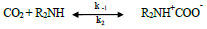
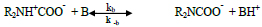
Based on Caplow's [23] studies, as per the zwitterion mechanism, CO2 can be absorbed into primary and secondary amines based on the following reactions:
 |
(R1) |
 |
(R2) |
Where R2NH represents the group that was previously attached to the amine group, while B represents a base molecule. Two essential steps of the mechanism include formation of CO2-amine zwitterion (carbamate) as an intermediate product (R1), followed by base-catalyzed deprotonation of this zwitterion (R2). When a base, such as RNH2, H2O, and OH-, is in the solution, it will catalyze the deprotonation of zwitterion [24].
Tertiary alkanolamines, such as methyldiethanolamine (MDEA) and triethanolamine (TEA), have slower reactivity with CO2 than the other groups of alkanolamines. However, the advantages of tertiary alkanolamines are high stoichiometric loading capacity, which is double the value of the primary amine group with 1 mol of CO2 /mol of amine [25], lower energy requirements for solvent regeneration [26], and lower corrosiveness to the processing equipment [27]. The following reaction between CO2 and a tertiary amine can produce bicarbonate ions;
 |
(R3) |
1.4.2. Sterically Hindered Amine
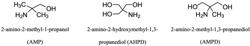
Sterically hindered amine (SHA) is a chemical compound with a bulky alkyl group attached to the amino group, which provides a steric hindrance to the reaction with CO2. Fig. (2) shows several types of sterically hindered amine structures. The steric group slows down the overall reaction, resulting in less stable carbamate production as an intermediate product. The SHA carbamates then undergo hydrolysis to form bicarbonate and release free amines for different reactions. Thus, the reaction between CO2 molecules and free amine molecules will increase the CO2 loading capacity of 1 mol of CO2/mol of amine [28]. Since SHA forms unstable carbamates, the regeneration energy used to absorb CO2 is lower than primary and secondary amines [29-31].
The use of SHA as an absorbent for acid gas removal was reported by EXXON Research and Engineering Company [28]. A type of SHA, 2-amino-2-methyl-1-propanol (AMP), received much attention from researchers due to its desirable characteristics as an absorbent for CO2 absorption. AMP was reported to have better properties compared with MEA, such as higher CO2 absorption capacity at 1.0 mol of CO2/mol of amine, lower energy required for the regeneration process [29, 30, 32, 33], and being more resistant to thermal degradation [29].
1.4.3. Activators
An activator is a reactive compound that reacts with CO2 with high reactivity. The blend of activators with amines can substantially solve the slow reactivity problem of several amine-based solvents. Cyclic amines were identified to have a higher prospect as the potential compound for CO2 capture because they show excellent performance with a greater CO2 absorption rate and capacity [34]. Several cyclic amines, such as piperazine (PZ), 2-(1-piperazinyl)-ethylamine (PZEA), morpholine (MORPH), and piperidine (PD), were reported to be activators in tertiary amine and SHA solvents for CO2 absorption.
PZ is the most common activator used in the activated MDEA technology of BASF. Due to the structure of cyclic and diamine of PZ, it exhibits a higher reaction rate than the primary and secondary amines [35]. It is a fast activator whose reaction rate constant is higher than MEA [35, 36]. As a secondary diamine, PZ can form dicarbamate, deprotonate, or a combination of the two [37]. Due to its solubility limitation in water, most studies use PZ as a promoter in small weight increments ranging from 1 to 10 wt.% [38]; for example, to enhance tertiary amine and SHA for CO2 absorption.
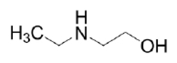
Other than that, 2-(ethylamino)ethanol (EAE), a sterically hindered secondary alkanolamine, has also been explored as an activator [39-42]. Fig. (3) depicts the molecular structure of EAE. Based on previous literature, EAE has shown excellent characteristics of CO2 absorption, such as higher absorption capacity compared to MEA solvent [41, 43, 44] and low energy consumption [40, 41, 44].
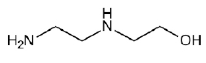
Besides, 2-((2-Aminoethyl) amino) ethanol (AEEA) is a diamine compound with a molecular structure consisting of primary and secondary amine groups. The molecular structure of AEEA is shown in Fig. (4). This diamine is one of the alternative activators that can potentially increase the absorption rate [45-47]. The high absorption capacity for CO2 can be observed using AEEA due to its CO2 loading capacity of 2 mol of CO2/mol of AEEA [47]. In the experimental studies by Zoghi et al. [46], CO2 absorption was observed for different activators (AEEA, AMP, DGA, DIPA, and PZ) added to the MDEA solvent. MDEA activated by AEEA exhibited the best CO2 absorption performance. Besides, they also reported the absorption performance to be influenced by the activator concentration. Thus, the molar ratio of the blended solvents is a significant factor that needs to be considered to enhance the CO2 absorption process.
1.4.4. Current Research Trends in Amine-Based Solvents
As mentioned in the previous sections, some single amines have shown remarkable performances and have been industrially accepted for the CO2 removal process. However, these solvents have limitations that need to be considered, such as low CO2 loading capacity and highly corrosive nature that can degrade equipment. Due to this, researchers have been focused on finding new alternative solvents that can be used as ideal solvents.
Numerous studies of blended amines as absorbents can be found in the literature to enhance the absorption process. Two or more groups of amine solvents were blended to complement each other by correcting the drawback of each single amine solvent. In most literature studies, the performances of blended amine solvents were reported to be superior compared to single amine solvents used in the CO2 removal process [48-51].
Moreover, one of the important developments in alkanolamine technology is the use of activators in aqueous alkanolamine solution to enhance the overall CO2 absorption rate [52]. There is recent interest in using an activator that has shown increments in the absorption performance. The advantages of each solvent complement each other to achieve the characteristic of an ideal solvent. Additionally, Jiang et al. [53] successfully proved the improvement of CO2 capture in a coal-fired power plant in terms of process performance and operational cost. Although the increase in heat duty was slightly observed from 3.54 GJ/ton (90% efficiency) to 3.82 GJ/ton CO2 (for 99.7% efficiency), better economic performance with CO2 was proven to avoid the cost of $64.1–64.8/tonne CO2, which is only $0.2–0.7/tonne CO2 higher than 90% efficiency. Based on previous experimental studies, the solvent activated by PZ has proven to increase the CO2 removal efficiency [52, 54-63]. The role of PZ as a rate activator is significantly important in elevating the reaction rate with CO2. Recently, the performances of other potential activators have also been explored, such as the addition of AEEA and EAE to form a blended solution for the CO2 removal process [40, 45, 64-66].
Active research development summary related to the field of CO2 absorption is given in Table 4. Current research studies cover a broad range of topics, such as physical properties [56, 67-69], CO2 solubility [39, 45, 54, 57, 58, 61, 67, 70], kinetic reaction [40, 60, 55] and mass transfer studies in a gas liquid contactor [39, 44, 67, 70-73]. The processes were evaluated on lab scale [39, 40, 45, 54, 61, 68-72] and pilot scale [59, 74] at atmospheric conditions considering flue gas treatment. Only a few works studied the physical properties of CO2 solubility [56, 57, 75] and mass transfer [76-80] conducted at high pressure conditions.
1.5. Mass Transfer in a Packed Absorption Column
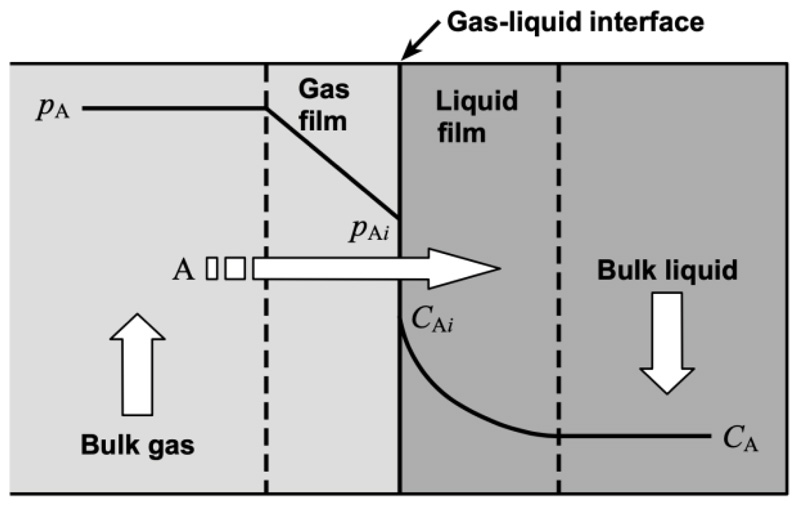
A packed absorption column is a gas-liquid contactor packed with structured or random packing. It is one of the mass transfer unit operations in which the behavior of the process is influenced by the mass transfer, thermodynamics, kinetics, and hydrodynamics in the packed column. In separation processes, the diffusion rate in both phases usually affects the total mass transfer rate. Fig. (5) shows the straight mass transfer (without chemical reaction) explained by the two-film theory, in which a gas-liquid interface is present between the gas and liquid films. The components pass through the gas and liquid films with molecular diffusion through each film, which is the controlling factor in the mass transfer process.
| Solvent | Process Equipment | Process Conditions | Process Performance Studies | Ref. |
|---|---|---|---|---|
| PZ+AMP | Packed column Wetted wall column |
PCO2 = 10 – 15 kPa T = 298 – 308 K PCO2 = 5 – 15 kPa T = 298 – 313 K |
Regeneration performances, specific absorption rate, CO2 loading capacity, and CO2 absorption (%) Kinetic (reaction rate) |
Khan et al. [54], Khan et al. [55], |
| PZ+AMP | Densitometer, Viscometer, Refractometer Stirred cell |
T = 298 – 333 K PTotal up to 6.06 MPa T = 298 – 333 K |
Physical properties Solubility studies |
Murshid et al. [56] Murshid et al. [57] |
| PZ+AMP | Wetted-wall column |
PCO2 = 18.03 – 72.52 kPa T = 293.15 – 323.15 K |
CO2 solubility, CO2 loading capacity | Mojtaba & Alireza [58] |
| PZ+AMP | Absorption column (pilot scale) |
PCO2= 11 – 13 kPa T = 313 K |
Pilot-scale performance (CO2 recovery, mass transfer coefficient, reboiler heat duty) | Artanto et al. [59] |
| PZ+AMP | Stopped flow equipment |
PCO2= 0 – 20 kPa T = 298 – 313 K |
Kinetic (reaction rate constant) |
Sodiq et al. [60] |
| PZ+MDEA | Packed column |
PCO2 = 10 – 15 kPa T = 298 – 313 K |
Regeneration efficacy, specific absorption rate, CO2 loading capacity and CO2 absorption (%) | Khan et al. [61] |
| PZ+MDEA | Packed column |
PCO2= 10 – 15 kPa T = 313.15 K |
Mass transfer and liquid hold-up correlations | Hemmati et al. [71] |
| PZ+DEEA | Hollow fiber membrane contactor |
PCO2= 10 – 20 kPa T = 298.15 – 318.15 K |
Mass transfer performance | Gao et al. [72] |
| MEA+IDMA2P | Stirred cell Equilibrium CO2 solubility measurement set up Packed column |
PTotal = 3 kPa T = 286.18 – 323.23 K PCO2 = 2 – 100 kPa T = 293.15 – 333.15 K PCO2 = 12 – 20 kPa T = 293.15 – 333.15 K |
CO2 solubility, equilibrium CO2 solubility and mass transfer performance |
Ling et al. [67] |
| DEEA+MEA | Equilibrium CO2 solubility measurement set up Packed column |
PCO2 = 6 – 100 kPa T = 303.15 – 343.15 K PCO2 = 6 – 18 kPa T = 303.15 – 343.15 K |
Mass transfer performance, equilibrium CO2 solubility | Liao et al. [70] |
| EAE+3DMA1P | Stirred cell Tray tower |
PTotal = 101 kPa T = 303.2 – 323.2 K CO2 inlet = 15% PTotal = 101 kPa T = 303.2 – 323.2 K |
CO2 loading capacity, CO2 removal (%) | Fu et al. [39] |
| DMEA+MEA | Hollow fiber membrane contactor |
PCO2= 10 - 20 kPa T = 298.15 – 318.15 K |
Mass transfer performance, molar ratio | Zhang et al. [73] |
| EAE+1DMA2P | Stopped-flow technique | T = 298.15 – 318.15 K | Kinetic (reaction rate constant) | Gao et al. [40] |
| AEEA+HMPD | CO2 solubility and absorption rate measurement set up |
PCO2= 28 – 1980 kPa T = 303.15 – 375.15 K |
CO2 solubility and absorption rate | Maleki & Motahari [45] |
This theory assumes that the overall resistance to mass transfer achieves equilibrium, which can be calculated by adding the resistance at the interface of each phase, as shown in Eq. (1) [82]:
 |
(1) |
Where Ky is the overall mass transfer coefficient in the gas phase, av is the effective mass transfer area of the packing, and m is the slope of the equilibrium curve. The term 1/Kyav is the overall mass transfer resistance, while 1/kyav and m/kxav represent the resistance in the gas and liquid films, respectively.
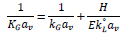
For CO2 absorption into a chemical solvent, the reaction occurs when CO2 in the gas stream diffuses into the liquid stream. Consequently, the resistances of the mass transfer and chemical reaction steps need to be included in the overall expression of the mass transfer rate [82]. The two-film theory is commonly used to describe the diffusion and chemical reactions between phases [82]. Eq. (2) expresses the correlation between the overall volumetric gas-film coefficient based on a partial pressure driving force (KGav) and the coefficients of each phase. This correlation is followed by related chemical reactions that are expressed as a function of the enhancement factor (E);
 |
(2) |
Where kGav represents the individual volumetric mass transfer coefficient for the gas based on the partial pressure driving force, H is Henry’s law coefficient and k°Lαv is the liquid phase mass transfer coefficient without chemical reactions. E is the value of mass transfer flux with chemical reaction divided by the mass transfer flux without chemical reaction. KGav and Kyav are related viaKGav = Kyav /P, where P is the total pressure inside the absorption column.
1.5.1. Determination of Overall Mass Transfer Coefficient for Dilute CO2 Concentrations in the Feed Gas
Generally, a gas mixture in the form of solute (CO2) and inert gas goes into the inlet at the bottom of the absorption column. A decrease in gas flow rate is expected as the gas flows through the column and encounters CO2 molecules in the gas phase, which shift into the liquid phase during the absorption process. If the bulk gas contains less than 10% of CO2, changes in the total gas flow rate and liquid flow rate during the absorption process are usually ignored due to insignificant changes in both flow rates [82].
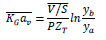
KGav for dilute gas with low CO2 content (< 10% CO2) in the gas stream is calculated as follows [82]:
 |
(3) |
Where V is the total gas flow rate, S is the cross-section area of the absorption column, and ZT is the packing height in the column. Meanwhile, ya and yb are the CO2 mole fractions at the outlet and inlet of the column, respectively.
1.5.2. Determination of Overall Mass Transfer Coefficient for High CO2 Concentrations in the Feed Gas
When CO2 concentrations are high in the binary gas mixture, changes in the flow rates during the operation must be considered. For higher than 10% of CO2 concentration, the material balance for the changes in the total gas and liquid flow rates in the column must be accounted for [82]. Any change in the total gas flow rate would be significant due to the inert gas concentration that varies between 10% to 90% as it flows from the bottom to the top of the column. Due to the significant decrease in the gas flow rate, the value of the gas flow rate is averaged  , which results in average
  , as shown in the following equation:
 |
(4) |
1.6. Influence of Process Parameters on Process Performance in the Packed Absorption Column
A summary of previous research that used different types of single amine and blended amine solvents for CO2 absorption conducted in packed absorption columns is shown in Table 5. It can be observed that the studies were conducted using different sizes of absorption columns, types of packing, and process conditions. In addition, all studies reported the effect of different parameters in the packed absorption column, for example, CO2 partial pressure, the total flow rate of gas and liquid, amine concentration, and inlet liquid temperature. The previous studies summarized in Table 5 are further discussed in the following subsections.
1.6.1. CO2 Partial Pressure in the Feed Gas
CO2 partial pressure (PCO2) in the column can be achieved by manipulating the total pressure in the column (PT) and the desired CO2 concentration in the feed gas (yco2). The relationship is shown in the following equation:
 |
(5) |
Theoretically, the increase in CO2 partial pressure resulted in higher amounts of CO2 molecules reacting with limited free active amines in the liquid phase. This condition created high resistance in the liquid phase, which consequently reduced the CO2 removal efficiency and the value of KGav. For simulated flue gas treatment, most of the studies were performed in the range of 1 – 20 kPa in PZ + AMP [54], PZ + MDEA [61], MEA + 1DMA2P [67], DEEA + MEA [70], MEA + MeOH [74], MDEA + MEA [83], DETA [87], DEEA [90], MEA + MeOH [91], MEA [95], and MEA + AMP [96]. The operations are categorized as low CO2 partial pressure conditions, in which all studies reported the reduction of KGav with increasing CO2 partial pressure of up to 20 kPa.
| Solvents | Characteristics of Packed Column | Process Parameters | Ref. |
|---|---|---|---|
| MDEA + MEA | ID = 0.275 m H = 2.15 m Packing: DX structured packing |
G = 15.99 – 18.65 kmol/m2.hr L =2.8 – 5.0 m3/m2.hr PCO2 = 0 – 15 kPa [MDEA/MEA] = 27/3, 25/5 and 23/7 wt.% T = 294 – 318 K CO2 loading = 0.05 – 0.28 |
Sema et al. [83] |
| MDEA + MPDA AMP + MPDA |
ID = 0.125 m Packing: Mellapak 250.Y Packing height: 4.2 m |
G = 30 – 110 kg/hr L = 4 – 28.5 m3/m2.hr PCO2 = 35 – 135 mbar T = 313 K CO2 loading = 0.179 – 0.213 |
Mangala-pally et al. [84] |
| DETA | ID = 0.024 m Packing: Dixon ring Packing height: 1.40 m |
G = 28.78 – 46.62 kmol/m2.hr L = 3.98 m3/m2.hr PCO2 = 14.8 – 15.3 kPa [Amine] = 2.0 kmol/m3 T = 303 K CO2 loading = 0.179 – 0.213 |
Fu et al. [85] |
| MEA | ID = 0.024 m Packing: Dixon ring Packing height: 1.4 m |
G = 24.98 – 39.45 kmol/m2.hr L = 3.98 m3/m2.hr PCO2 = 15.1 – 15.8 kPa [Amine] = 2.0 kmol/m3 T = 303 K CO2 loading = 0.179 – 0.213 |
Fu et al. [85] |
| DEAB MEA MDEA |
ID = 0.275 m H = 2.15 m Packing: DX structured packing |
G = 17.85 kmol/m2.hr L =4.0 – 7.0 m3/m2.hr PCO2 = 9.0 kPa [Amine] = 2.0 kmol/m3 T = 296.35 K CO2 loading = 0.14 |
Naami et al. [86] |
| DETA | ID = 0.028 m H = 1.7 m Packing: DX structured packing Packing height: 1.2 m |
G = 22.2 – 40.4 kmol/m2.hr L = 1.95 – 4.87 m3/m2.hr PCO2 = 14.8 – 15.3 kPa [Amine] = 1.0 – 3.0 kmol/m3 T = 303.15 – 323.15 K CO2 loading = 0.184 – 0.826 |
Fu et al. [87] |
| MEA | ID = 0.211 m H = 9.4 m Packing: Pall rings Packing height: 2.7 m |
G = 100 – 140 m3/ hr L =0.24 – 0.42 m3/hr PCO2= 10 - 11 kPa [MEA] = 30 wt.% T = 313.15 K |
Artanto et al. [88] |
| PZ+AMP | ID = 0.211 m H = 9.4 m Packing: Pall rings Packing height: 2.7 m |
G = 100 – 140 m3/ hr L =0.24 – 0.54 m3/hr PCO2= 11 – 13 kPa [AMP/PZ] = 25/5 wt.% T = 313.15 K |
Artanto et al. [59] |
| MEA AMP |
ID = 0.04 m H = 1.30 m Packing: nonreactive metal HELI-PAK |
G = 0.005 – 0.008 m3/min L =0.00015 – 0.0003 m3/min PCO2 = 10.64 – 12.66 kPa [Amine] = 1, 2, 3 kmol/m3 T = 303 K |
Khan et al. [89] |
| PZ+AMP | ID = 0.04 m H = 1.3 m Packing: nonreactive metal HELI-PAK |
G = 0.005 – 0.008 m3/min L =0.00015 – 0.0003 m3/min PCO2 = 10 – 15 kPa [AMP/PZ] = 28/2, 25/5, 22/8, 20/10 wt.% T = 298 – 308 K |
Khan et al. [54] |
| PZ+MDEA | ID = 0.04 m H = 1.3 m Packing: nonreactive metal HELI-PAK |
G = 0.005 – 0.008 m3/min L =0.00015 – 0.0003 m3/min PCO2 = 10 – 15 kPa [AMP/PZ] = 28/2, 25/5, 22/8, 20/10 wt.% T = 298 – 308 K |
Khan et al. [61] |
| MEA+ 1DMA2P |
ID = 0.028 m H = 1.7 m Packing: Sulzer DX structured packing Packing height: 1.25 m |
G = 33.49 – 48.07 kmol/m2.hr L =2.92 – 5.85 m3/m2.hr PCO2 = 12 – 20 kPa T = 293.15 – 333.15 K CO2 loading = 0.20 – 0.44 |
Ling et al. [67] |
| DEEA | ID = 0.028 m H = 1.70 m Packing: Sulzer DX structured packing Packing height: 1.25 m |
G = 30.50 – 43.52 kmol/m2.hr L =3.9 – 11.7 m3/m2.hr PCO2 = 3 – 15 kPa [Amine] = 1 – 4 kmol/m3 T = 293.15 – 333.15 K CO2 loading = 0.05 – 0.20 |
Xu et al. [90] |
| DEEA+MEA | ID = 0.028 m Packing: Sulzer DX structured packing Packing height: 1.25 m |
G = 30.47 – 47.87 kmol/m2.hr L =3.9 – 11.7 m3/m2.hr PCO2 = 6 – 18 kPa [Amine] = 2 – 5 kmol/m3 T = 303.15 – 343.15 K CO2 loading = 0.15 – 0.35 |
Liao et al. [70] |
| MEA+MeOH | H = 2.5 m Packing: Sulzer packing 500 BX Pall rings packing Mellapale packing 500Y Packing height: 1.1 m and 0.9 m (two packed section) |
G = 3 – 5 m3/hr L = 30, 40 L/hr T = 293.15 K [CO2] = 15 vol.% |
Gao et al. [74] |
| MEA+MeOH | ID = 0.028 m H = 1.7 m Packing: DX structured packing Packing height: 1.25 m |
G = 24.37 – 63.54 kmol/m2.hr L =2.92 – 16.09 m3/m2.hr PCO2 = 6.7 – 13.8 kPa [Amine] = 2.5 – 5 kmol/m3 T = 283. 15K CO2 loading = 0 – 0.373 |
Fu et al. [91] |
| 1DMA2P, MEA, MDEA |
ID = 0.028 m H = 1.7 m Packing: DX structured packing Packing height: 1.25 m |
G = 28.02 kmol/m2.hr L = 4.87 m3/m2.hr PCO2 = 13.2 – 13.6 kPa [Amine] = 2 kmol/m3 T = 313 K |
Liang et al. [92] |
| MEA | ID = 0.046 m H = 2.04 m Packing: Sulzer metal gauze packing |
G = 18.89 – 35.08 kmol/m2.hr L = 3.0 – 7.5 L/hr [CO2] = 20% PCO2 = 1000 kPa [Amine] = 1.0 – 4.0 kmol/m3 T = 300 – 318 K Operating pressure = 5.0 MPa |
Halim et al. [93] |
| PZ+AMP | ID = 0.046 m H = 2.04 m Packing: Sulzer metal gauze packing |
G = 33 – 51 kmol/m2.hr L = 2.89 – 3.97 m3/m2.hr [CO2] = 40 vol.% [AMP/PZ] = 23/7 wt.% T = 303 – 318 K Operating pressure = 0.1 – 4.0 MPa PCO2 = 40 – 1600 kPa |
Hairul et al. [79] |
| PZ+AMP | ID = 0.046 m H = 2.04 m Packing: Sulzer metal gauze packing |
G = 33 – 51 kmol/m2.hr L = 2.89 – 4.33 m3/m2.hr [CO2] = 30 – 50% PCO2=1212 kPa – 2020 kPa [AMP/PZ] = 20, 30, 40, and 50 wt.% T = 303 – 318 K Operating pressure = 0.1 – 5.0 MPa |
Hairul et al. [77] |
| MEA+NMP | ID = 0.145 m Packing height: 1.0 m Packing: FLEXIPAC 1Y structured packing |
G = 100 SLPM L = 1.0 L/min [CO2] = 50% [NMP/MEA] = 40/20 wt.% Operating pressure = 0.1 – 5.0 MPa PCO2 = 50 – 2500 kPa |
Tan et al. [94] |
Meanwhile, NG processing requires a high-pressure operation of up to 5.0 MPa, which requires high CO2 partial pressure conditions. Several studies were conducted using CO2-rich NG in the range of 20% to 75% of CO2 for NG processing applications [77, 79, 93, 94]. It was observed that different experimental designs resulted in different observations at high CO2 partial pressures. Since CO2 partial pressure can be achieved by manipulating one of the factors in Equation 5, the effect of CO2 concentration and operating pressure has been reported in previous studies. Although both studies resulted in various ranges of CO2 partial pressure, they also changed the CO2 gas flow rate (GCO2) of the system. Significant trend in CO2 removal efficiency was reported by Hairul et al. [78], Halim et al. [79], and Tan et al. [94].
Hairul et al. [78] studied CO2 absorption using feed gas consisting of 30% to 50% CO2 in NG at 4.0 MPa, with 7 wt.% PZ + 23 wt.% AMP blended solution as the absorber. Different CO2 partial pressures (1.2 to 2.0 MPa) were used, while the CO2 gas flow rate was consequently varied from 12 to 20 kmol/m2.h during the operation. With a fixed liquid flow rate, the Lamine/GCO2 ratio was decreased in this study. The experimental results showed that the CO2 removal efficiency (%) reduced from 100% to 38%, while the KGav reduced from 26 to 2 mol/m3.hr.kPa. The authors concluded that the decrease in the Lamine/GCO2 ratio reduced the performance at high CO2 concentrations due to the increase of liquid film resistance. The reduction in performance is in agreement with trends at low CO2 partial pressure conditions.
Halim et al. [79] studied the influence of different operating pressures, ranging from 0.1 to 4.0 MPa, with 40% of CO2 in the feed gas. This condition consequently varies the CO2 partial pressure in the range of 40 to 1600 kPa. The CO2 gas flow rate was constant at 13.27 kmol/m2.h during the operation. The CO2 removal efficiency using the PZ + AMP blended solution was reportedly increased from 52% up to 88%, while the overall mass transfer coefficient based on mol fraction driving force (Kyav) increased from 10 to 28 kmol/m3.hr as the total column pressure increased. It was observed that only slight increments in the Kyav were noted for the 0.1 to 2.0 MPa range, while the performance was significantly improved in the range of 2.0 to 4.0 MPa. This observation was made based on the increasing mole fraction driving force at higher pressure conditions [82]. In addition, CO2 solubility in the blended solution increased at higher pressure (up to 6.0 MPa) [56, 57].
A significant improvement at higher operating pressure was also reported by Tan et al. [94], in which CO2 absorption from NG was conducted using 20 wt.% MEA + 40 wt.% NMP blended solution. The CO2 partial pressure was set to range between 50 to 2500 kPa. A pilot-scale column with 0.1 to 5.0 MPa operating pressure was utilized by flowing 50% CO2 in NG as the feed gas to the column. The CO2 gas flow rate supplied to the system was constant in each experiment. The CO2 removal percentage was improved from 65% to a complete removal (100%) with the increased CO2 partial pressure. This behavior indicates a significant influence of operating pressure and CO2 partial pressure in the packed column operation for the CO2 absorption process.
1.6.2. Gas Flow Rates
The gas flow rates conducted in CO2 absorption studies were mostly discussed in terms of the effect of inert gas flow rates [54, 61, 67, 70, 85, 87, 90, 91, 93, 79, 97, 98]. The effect of inert gas flow rates at atmospheric conditions in the range of 9 to 15 kPa CO2 partial pressure was reported to be insignificant in the process [54, 85, 87, 90, 97], while some others showed a trend of decreasing performance with the gas flow rate [70, 91].
According to Xu et al. [90], in experimental studies using 3 kmol/m3 of DEEA as absorbent, KGav was nearly constant for both CO2 partial pressures (conducted at 9 kPa and 15 kPa) when the gas flow rate was increased from 26.1 to 43.5 m3/m2.hr. The authors explained that the observed performance was due to the reaction of active amines with CO2 molecules on the surface of the liquid film, with the changes of kG in the gas film neglected in accounting for the KGav value. Thus, increasing the gas flow rate does not affect the absorption process. Ling et al. [67] made a similar observation in a study on CO2 absorption into MEA + 1DMA2P blended solution at different inert gas flow rates ranging from 33.49 to 48.07 kmol/m2.hr. KGav was reported to be approximately 0.7 kmol/m3.hr.kPa.
Distinct behaviors of the KGav in two regions of gas flow rate were reported by Yan et al. [98]:
1. The change in KGav was insignificant, with the increase in gas flow rate ranging from 20 to 37.5 kmol/m2.hr. This result was due to the mass transfer being controlled by the liquid phase. Thus, any changes in the gas phase have no substantial effect on the process performance.
2. The gas flow rate increased beyond 37.5 kmol/m2.hr and resulted in a significant decrease in KGav values. This behavior could be due to the high gas velocity, decreasing the spread of liquid on the packing surface.
Fu et al. reported the distinctive behavior of inert gas with different flow rates in the absorption of CO2 in diethylenetriamine (DETA) and MEA solutions [85] at a constant CO2 partial pressure of 15 kPa. In their experimental studies, as the inert gas flow rate increased from 25 – 45 kmol/m2.hr, insignificant changes in KGav values were observed for both solvents due to negligible resistance in the gas phase [85]. However, a significant decrease in KGav from 1.9 to 0.75 kmol/m3.hr.kPa was observed with increased inert gas flow rate (24.37 to 63.54 kmol/m2.hr) for the CO2 – MEA + MeOH system [91].
Khan et al. [61] reported CO2 absorption of four different blends of PZ + MDEA (2/28, 5/25, 8/22, and 10/20 wt.%/wt.%) conducted at 15 kPa of CO2 partial pressure condition. The decreased CO2 removal efficiency was reported for all four blends of PZ + MDEA when the gas flow rate was increased from 230.78 to 369.23 m3/m2.hr. Decreased absorption efficiency from 76.86% to 68.34% was observed for a blend of 10 wt.% PZ + 20 wt.% MDEA. At higher gas flow rates in the column, the contact time between the two phases was reduced for the reaction to occur, thus resulting in lower absorption efficiency.
Besides the influence of gas flow rate at low CO2 partial pressure conditions, CO2 absorption has also been reported based on KGav values and removal efficiency at high CO2 partial pressure conditions. Hairul et al. [93] performed the experimental studies for CO2 absorption into 2 kmol/m3 of MEA solution at 1010 kPa of CO2 partial pressure, and the process was conducted at different gas flow rates ranging between 18.89 and 35.08 kmol/m2.hr. The KGav was observed to be minutely increased from 1.27 to 1.32 mol/m2.hr.kPa, with an increased gas flow rate. This result was based on the absorption process being controlled by the liquid phase; hence changes in the gas phase left the process unaffected [93].
However, the trend was significantly different in their study of CO2 absorption into 7 wt.% PZ + 23 wt.% AMP blended solution for a higher range of gas flow rate conducted at 1616 kPa CO2 partial pressure [79]. The total gas flow rate varied from 33 to 51 kmol/m3.hr with variations in both CO2 and inert (NG) flow rates. KGav was significantly decreased from 6.8 to 2.6 mol/m2.hr.kPa in this experiment. The possible cause of the observation was due to the limited contact time for the reaction of CO2 and amine, which resulted in lowered absorption performance [79]. The increasing CO2 flow into the column increased the concentration of CO2 molecules, with a limited concentration of amine molecules in the liquid phase, thus, limiting the reaction between CO2 and amine molecules.
1.6.3. Liquid Flow Rate
Liquid flow rate can be reported as a single effect or as a ratio of liquid and gas flow rates (L/G ratio). In this study, the L/G ratio was controlled by varying the liquid flow rates with a fixed gas flow rate in the column. In a counter-current packed column, the L/G ratio is an important factor that can enhance absorption efficiency. Theoretically, the increase of driving force results from the increasing L/G ratio in the column except in the upper part of the absorption column [82]. Nevertheless, to reduce the cost of circulation and energy required for the liquid regeneration process, the liquid flow rate for the absorption process should be optimized [83, 99, 100]. A significant impact of the L/G ratio was observed in the absorption processes by Artanto et al. [59], Mangalapally et al. [84, 101], Godini and Mowla [102], Denca et al. [103], and Kumar et al. [104].
The influence of liquid flow rate on absorption has been reported by many researchers based on KGav values [67, 70, 74, 91, 83, 86, 90], specific absorption rate [42, 59], 76] and removal efficiency [54, 74, 105] for low CO2 partial pressures ranging from 10 to 15 kPa. Based on the literature, increasing liquid flow rate will increase KGav values in a CO2 absorption process because of the following possible reasons:
1. The process is controlled by the liquid phase, and kL is directly proportional to KGav [106, 107];
2. The surface of wet packing is increased, which results in increased interfacial area (av) between gas and liquid [83, 86, 91, 95, 106]; and
3. The higher capacity of CO2 is due to the increase of free amines in the system resulting in higher KGav values [66, 67, 91, 106, 107].
Fu et al. [91] reported the increase of KGav with an increased liquid flow rate (2.92 to 14.63 m3/m2.hr) at two different concentrations of MEA – MeOH blended solution (2.5 and 5.0 kmol/m3) for CO2 absorption at 13.4 kPa of CO2 partial pressure. KGav increased from 0.3 to 3.2 kmol/m3.hr.kPa using 5.0 kmol/m3 of the solvent concentration, and KGav increased from 0.29 to 1.4 kmol/m3.hr.kPa using 2.5 kmol/m3 of the solvent concentration. They explained that the mass transfer was controlled by the liquid film resistance, which was reduced with increasing liquid flow rate [91]. Meanwhile, according to Ling et al. [67], CO2 absorption was performed using MEA + 1DMA2P blended solution at 13.4 kPa of CO2 partial pressure, with a liquid flow rate ranging between 2.92 and 5.85 m3/m2.hr. The authors stated that the increase of KGav from 0.4 to 1.8 kmol/m3.hr.kPa was observed due to a greater effective contact area for the reaction at higher liquid flow rates.
Xu et al. [90] studied the absorption process using 3 kmol/m3 of DEEA solution for 0.1 and 0.3 mol/mol of lean CO2 loading at different liquid flow rates (3.9 to 11.7 m3/m2.hr). CO2 absorption into DEEA was conducted at 15 kPa of CO2 partial pressure. At higher liquid flow rates, the KGav for amine solution with 0.1 mol/mol CO2 loading was slightly increased from 0.15 to 0.18 kmol/m3.hr.kPa. For the solution with 0.3 mol/mol CO2 loading, the highest value of KGav was 0.13 kmol/m3.hr.kPa. Thus, CO2 absorption at 0.1 mol/mol lean CO2 loading with the highest KGav value of 0.18 kmol/m3.hr.kPa was proven effective for their system.
Liao et al. [70] conducted experimental studies on CO2 absorption at atmospheric pressure using MEA + DEEA blended solution. KGav was significantly increased from 0.55 to 1.0 kmol/m3.hr.kPa, with an increasing liquid flow rate from 3.9 to 8.7 m3/m2.hr. However, KGav was observed to have a slightly decreasing trend from 1.0 to 0.9 kmol/m3.hr.kPa beyond 8.7 m3/m2.hr to 11.7 m3/m2.hr of liquid flow rate. The reduction of KGav in this experiment was explained by the wall-flow phenomenon in the process [70]. In some studies, the mass transfer performance was found to be decreased at high liquid flow rates in the absorption column due to the formation of bubbles, affecting the effective surface area of the internal packing [84]. It was also reported that there was no bubble formation when the liquid flow rate ranged between 2.8 and 5.0 m3/m2.hr [84].
The CO2 absorption process was further investigated based on the effect of higher liquid flow rates on NG processing applications. Halim et al. [79] studied the effect of liquid flow rate on CO2 absorption into 7 wt.% PZ + 23 wt.% AMP blended solution at 4.0 MPa and CO2 partial pressure of 1600 kPa. The KGav value was increased from 0.8 to 3.6 mol/m3.hr.kPa when the liquid flow rate was increased from 1.81 to 4.51 m3/m2.hr. This phenomenon was also observed in their experimental study on CO2 absorption into 2 kmol/m3 MEA solution at 1010 kPa of CO2 partial pressure [93]. The authors reported that similar results were obtained at high CO2 partial pressures as those found in low CO2 partial pressures. They concluded that at higher liquid flow rates, mass transfer was increased due to the availability of more free amines to react with CO2 molecules, leading to a reduction in liquid film resistance, which resulted in higher mass transfer performance.
1.6.4. Concentration of Amine Solution
In the past decades, numerous studies have reported that removal behavior can be affected by amine concentration. Most of the studies found that KGav increases with increasing amine concentrations within a range of 0 – 5.0 mol/L [66, 70, 85, 91, 95, 108]. At higher amine concentrations, the availability of free active amine per unit volume is increased. This would accelerate the reaction rate between amine and CO2 molecules. Nevertheless, at higher solvent concentrations, it will lead to an increase in solution viscosity to some extent, thereby reducing molecular diffusion rate [70, 85]. In addition, as the solvent viscosity increases, the area of the solvent spread on the surface of the packing is reduced [95].
Liao et al. [70] performed experimental studies using DEEA + MEA blended solution on the CO2 absorption process at different amine concentrations. From their study, an optimal chemical concentration was observed at 2.75 kmol/m3. Increasing KGav value from 0.55 to 1.08 kmol/m3.hr kPa was reported when the chemical concentration was increased (2.0 to 2.75 kmol/m3). Meanwhile, when the chemical concentration was increased beyond 2.75 kmol/m3, the KGav decreased to 0.8 kmol/m3.hr kPa.
An interaction study on MEA concentrations in the range of 3.0 – 7.0 mol/L and temperatures in the range of 303 – 323 K found that at higher MEA concentrations and temperatures, an increase of mass transfer efficiency was noted due to the domination of the kinetic effect over the viscosity effect at high MEA concentrations and temperatures [95]. The increase of MEA concentration at higher temperatures led to small increments in MEA viscosity, which resulted in less interference with the kinetic effect at increasing concentrations of MEA.
Besides that, the optimization of amine concentration is required for the absorption process, as concentration is proportional to the increase in solvent cost and corrosivity [106]. Due to the problem of corrosion in the pipelines and processing equipment, the lean-rich heat exchangers, reboiler, and strippers are primarily affected. The amine concentration used in industrial applications depends on the corrosive nature of amine-based solvents; for example, the optimum concentration for MEA was 30 wt.%, while the concentration for MDEA was limited to up to 60 wt.% [109].
In high operating pressure conditions with CO2 partial pressure within 1000 kPa to 1600 kPa, previous research studies reported that the performance of CO2 absorption was superior for amine concentrations in the range of 20 to 40 wt.% [79, 93]. The findings were discussed in terms of the high availability of amines for the reaction with CO2 molecules at higher amine concentrations, thus leading to higher enhancement factors, E. The higher removal efficiency was also explained by the reduction of liquid film resistance at higher amine concentrations [79, 93].
1.6.5. Inlet Temperature of Liquid
The effect of inlet liquid temperature on CO2 absorption process at low CO2 partial pressures ranging between 10 to 15 kPa was studied by several researchers [54, 83, 87, 105, 95, 96, 110]. The reaction rate constant, k, is a significant parameter in the kinetics of the reaction between CO2 and amine molecules. As the temperature increases, the k value also increases due to the higher reaction rate. Xu et al. [90] reported CO2 absorption into 3 kmol/m3 of DEEA solution, where KGav was reported to be increased when the inlet temperature was higher (273 K to 333 K). Increased mass transfer can be explained by the decrease of solvent viscosity at higher inlet liquid temperatures, resulting in higher CO2 solubility [90].
In previous studies, KGav was found to increase with inlet liquid temperature during CO2 absorption into MDEA + MEA blended solution at 294-318 K [83] and diethylenetriamine (DETA) at 303-323 K [87]. In these studies, the effect of inlet liquid temperature was conducted only at three different points of temperature, specifically at 294, 303, and 318 K [83], and 303, 313, and 323 K [87]. No optimum temperature was reported in these studies. However, for CO2 absorption into MEA solution within a range of 298 to 318 K, the optimum temperature was reported in the range of 309 to 313 K [110]. The rise of inlet liquid temperature beyond 313 K and up to 318 K induced efficiency deterioration, which reduced KGav values by 10% [110].
Besides, in studies by Liao et al. [70], the optimum inlet liquid temperature for CO2 absorption in MEA + DEEA blended solution occurred at 313.15 K. The optimum temperature in their studies was explained by the reversible exothermic reaction for the absorption of CO2 into amine solvent. Furthermore, they also stated that the increase in absorption performance as the temperature increased up to 313.15 K resulted due to the increase in absorption rate at higher inlet liquid temperatures. At this point, the mass transfer performance reached the maximum point. The reversible reaction was dominant beyond this point up to 343.15 K [70]. According to Ling et al. [67], CO2 absorption into MEA + 1DMA2P blended solution increased the KGav value from 0.51 to 0.68 kmol/m3.hr.kPa when the inlet liquid temperature was increased from 293.15 K to 323.25 K. The performance was gradually reduced with the KGav value decreased to 0.61 kmol/m3.hr.kPa as the inlet liquid temperature increased to 333.15 K and was explained by reversible behavior at higher temperatures, as discussed in other studies [67, 70, 110, 111].
Apart from the influence of liquid temperature at low CO2 partial pressures, researchers are also interested in studying the influence of inlet liquid temperature at higher operating pressures for high CO2 partial pressures ranging from 1000 to 1600 kPa [79, 80]. Halim et al. [79] reported the optimum inlet liquid temperature for CO2 absorption into 7 wt.% PZ + 23 wt.% AMP blended solution at 313 K. In their study, the increasing trend of CO2 removal efficiency was observed when the inlet temperature was increased from 303 to 313 K due to the forward reaction being favored over the reversible reaction. However, when the inlet liquid temperature was increased beyond 313 K, the reversible reaction was favored, resulting in a decreased CO2 removal efficiency. Besides, in experimental studies by Tan et al. [76], Stonvent-II solvent was used for the CO2 absorption process at 750 kPa of CO2 partial pressure. The absorption performance was observed at different inlet liquid temperatures ranging between 308.15 and 318.15 K. The absorption performance was proven to be efficient at an inlet liquid temperature of 308.15 K. Although both inlet liquid temperatures showed 100% removal of CO2, CO2 removal was completed faster at 308.15 K compared to CO2 removal at 318.15 K. It was due to the increase of inlet liquid temperature leading to the changes of solvent physical solubility, and consequently, reducing the absorption efficiency [76].
CONCLUSION AND PROSPECTS
This review discussed recent studies on CO2 absorption at low and high CO2 partial pressure conditions, which were mainly focused on CO2 absorption for flue gas treatment, biogas enhancement, and natural gas processing. Based on the reviews, developing an ideal solvent is one of the focused areas to improve absorption performance. The topics of physical properties, equilibrium solubility, kinetic reaction, and mass transfer performance have been explored by many researchers and need to be considered before implementing the industrial-scale operation. Some blended solvents have been reported to have excellent characteristics and performance; however, a lack of research studies has been identified on the regeneration energy required for the desorption process. Thermal energy is required during the regeneration process to break the bonds between CO2 molecules and solvent molecules, which is one of the important factors to be considered because the increase in energy requirement can result in a higher operating cost of the process.
The studies of different amine-based solvents (single amine and blended amines) have been reviewed over different operating conditions involving low and high CO2 partial pressures. The influence of operating conditions on the absorption process in packed columns has been discussed in terms of CO2 partial pressure, gas and liquid flow rates, amine concentrations, and inlet liquid temperature. In terms of research studies at low CO2 partial pressure conditions, the mass transfer studies were dominated by flue gas treatment with a gap in discussion for biogas as the feed gas. Biogas application requires higher CO2 concentrations in the feed gas, producing higher CO2 partial pressures than flue gas treatment. A high CO2 partial pressure condition was adopted instead of NG processing, specifically for onshore and offshore operations. The depletion of conventional NG or sweet gas with low CO2 concentration motivates the oil and gas company to explore unconventional gas with higher CO2 concentrations (>10% CO2).
As discussed in this paper, mass transfer is an important aspect of the CO2–amine absorption system in which the optimum removal of CO2 in the process can be achieved by understanding the behavior of mass transfer in a packed column. Thus, mass transfer studies in packed columns need to be explored, not limited to the lab scale, but rather extended to pilot-scale operations for a potential absorbent with excellent characteristics. The pilot-scale data are useful for scaling up the process to industrial-scale operations. On the industrial scale, energy efficiency and cost-effective processes are the focused criteria for the separation process. Therefore, more fundamental studies need to be conducted to optimize the absorption process before it can be accepted for industrial operation.
ABBREVIATIONS AND NOMENCLATURE
| 1DMA2P | = 1-dimethylamino-2-propanol |
| 3DMA1P | = 3-dimethylamino-1-propanol |
| AEEA | = 2-((2-aminoethyl) amino)ethanol |
| AHPD | = Hydroxymethyl-1,3-propanediol |
| AMP | = 2-amino-2-methyl-1-propanol |
| AMPD | = 2-amino-2-methyl-1,3-propanediol |
| BASF | = Baden Aniline and Soda Factory |
| C2H6 | = Ethane |
| C3H8 | = Propane |
| C4H10 | = Butane |
| CH4 | = Methane |
| CO2 | = Carbon dioxide |
| DEA | = Diethanolamine |
| DEAB | = N,N-diethylaminobenzaldehyde |
| DEEA | = Diethylethanolamine |
| DETA | = Diethylenetriamine |
| DGA | = Diglycolamine agent |
| DIPA | = Diisopropanolamine |
| DMEA | = Dimethylethanolamine |
| EAE | = 2-(ethylamino)ethanol |
| H2 | = Hydrogen |
| H2O | = Water |
| H2S | = Hydrogen sulphide |
| HMPD | = 4-hydroxy-1-methylpiperidine |
| hr | = Hour |
| K | = Kelvin |
| kPa | = Kilopascal |
| kmol | = Kilomole |
| LNG | = Liquefied natural gas |
| MDEA | = Methyldiethanolamine |
| MEA | = Monoethanolamine |
| MeOH | = Methanol |
| mol | = Mole |
| m | = Meter |
| mm | = Millimeter |
| min | = Minute |
| MORPH | = Morpholine |
| MPa | = Megapascal |
| MPDA | = m-Phenylenediamine |
| N2 | = Nitrogen |
| NG | = Natural gas |
| NH3 | = Ammonia |
| NMP | = N-methyl-2-pyrrolidone |
| O2 | = Oxygen |
| PD | = Piperidine |
| PZ | = Piperazine |
| PZEA | = 2-(1-piperazinyl)-ethylamine |
| SHA | = Sterically hindered amine |
| SO2 | = Sulfur dioxide |
| SLPM | = Standard liter per minute |
| T | = Temperature |
| TEA | = Triethanolamine |
| vol. | = Volume |
| wt. | = Weight |
| av | = Effective mass transfer area, m2/m3 |
| CAi | = Molar concentration of solute A at the interface, mol/m3 |
| E | = Enhancement factor (dimensionless) |
| H | = Henry’s law coefficient, kPa/mol fraction |
| k2 | = Second-order reaction rate constant, m3/kmol.s |
| ky | = Mass transfer coefficient in the gas film |
| kx | = Mass transfer coefficient in the liquid film |
| k°Lαv | = Mass transfer coefficient for the liquid phase without chemical reactions |
| kGav | = Individual volumetric mass transfer coefficient for the gas phase based on partial pressure driving force, kmol/m3.hr.kPa |
| kyav | = Individual volumetric mass transfer coefficient for the gas phase based on unit mole fraction driving force, kmol/m3.hr.unit mole fraction |
| kxav | = Individual volumetric mass transfer coefficient for the liquid phase based on the unit mole fraction of driving force, kmol/m3.hr. unit mole fraction |
| Ky | = Overall mass transfer coefficient for the gas phase based on the unit mole fraction of driving force, kmol/m2.hr. unit mole fraction |
| KG | = Overall mass transfer coefficient for the gas phase based on the partial pressure of driving force, kmol/m2.hr.kPa |
| Kyav | = Overall volumetric mass transfer coefficient for the gas phase based on the unit mole fraction of driving force, kmol/m3 hr. unit mole fraction |
| KGav | = Overall volumetric mass transfer coefficient for the gas phase based on the partial pressure of driving force, kmol/m3.hr.kPa |
| m | = Slope of the equilibrium curve |
| P | = Total pressure, kPa |
| pA | = Partial pressure of solute A, kPa |
| pAi | = Partial pressure of solute A at the interface, kPa |
| S | = Cross-sectional area of the column, m2 |
| V | = Molar flow rate of gas, mol/hr |
| ya | = Mole fraction of component A in the bulk gas at the outlet of the column, mol/mol |
| yb | = Mole fraction of component A in the bulk gas at the inlet of the column, mol/mol |
| ZT | = Packing height (m) |
CONSENT FOR PUBLICATION
Not applicable
FUNDING
The authors would like to acknowledge the Ministry of Higher Education, Malaysia (MOHE), for the research fund under the Fundamental Research Grant Scheme (FRGS/1/2018/TK02/UNIMAP/02/5). The authors are also grateful to Universiti Teknologi PETRONAS and Universiti Malaysia Perlis for funding the research activities via the Joint Research Project (JRP8) and (9023-00022).
CONFLICT OF INTEREST
The authors declare no conflict of interest, financial or otherwise.
ACKNOWLEDGEMENTS
Declared none.