All published articles of this journal are available on ScienceDirect.
Industrial Manufacturing of Aqueous Solutions of Sodium Sulfhydrate (NaHS 43%) in a Multi-Phase Reactor
Abstract
Background:
This research deals with the manufacture of sodium sulphides and sodium sulfhydrate in an isothermal multiphase chemical reactor to produce concentrated aqueous solutions of sodium sulfhydrate (greater than 43%) through Gas-Liquid-Solid reactions from hydrogen sulfide and hydroxide of sodium at 50%.
Methods:
A method is proposed that integrates the recovery of hydrogen sulfide from an industrial chemical process where the H2S gas is generated as a sub product, the strategy of the developed process was integrated into a manufacturing plant of dithiophosphoric acids (ADTF) where it was possible to recover the hydrogen sulfide in the form of an aqueous solution of NaHS with a concentration higher than 43%.
Results:
The experimental tests showed that the biphasic reaction mixture formed by Na2S, NaHS and H2O with global compositions of 13.3%; 26.9% and 59.7% respectively, is appropriate to obtain 43% sodium sulfhydrate in a stirred tank reactor, operated at temperatures ranging from 50°C to 55°C, where gaseous hydrogen sulfide is continually bubbled.
Conclusion:
Sodium sulfide (specifically Na2S.5H2O crystals) of the biphasic mixture is produced from a solution of sodium sulfhydrate (43% NaHS) and aqueous sodium hydroxide (50% NaOH). The environmental problem generated by the H2S was solved with a 90% recovery in the multiphase reactor and 5% in the safety absorber.
1. INTRODUCTION
Hydrogen sulfide is a highly toxic gas [1, 2, 3]; with an offensive odour reminiscent of rotten eggs [4, 5] it is readily water soluble [3]. One of the problems caused by hydrogen sulfide with respect to the health and safety of personnel is the time and concentration of exposure. If exposed to 100 ppm H2S during 8 hours, people will hemorrhage and die. Concentrations above 600 ppm can be fatal if exposed between 3 and 5 minutes [6]. Exposure to H2S is highly dangerous and the sequelae that can appear in people who survive acute poisoning are generally neurological post-anoxic. Chronic exposure can cause chronic bronchitis and neuro-psychic symptoms [7]. Industrial emissions that contain low concentrations of hydrogen sulfide (less than 1 ppm) have odor problems [8] that affect the environment, and exposure to high concentrations (greater than 100 ppm) has effects on people’s health leading to fatal consequences, see www.osha.gov [9]. Chemical industries – especially those industries that generate high concentrations and volumes that affect the economy of the main process – are constantly searching for chemical control methods of these emissions and their final disposal. A method of chemical control of hydrogen sulfide gas consists of transforming it into stable substances with commercial value such as elemental sulfur [10, 11] or using processes that transform H2S without production of inorganic salt byproducts and wastewater [12] and stable aqueous solutions of sodium sulphide and sodium sulfhydrate and other salts [13, 14]. In the oil and gas industry there are advanced treatment of acid gases (H2S) where seven ways to remove H2S from crude oil and gas are described [15]. Absorption is used in the oil & gas industry to remove H2S and carbon dioxide from sour natural gas and refinery gas. This removal is called gas sweetening, which consists in the transfer of H2S from the gas phase to the liquid phase [16]. Caustic scrubbing is a technology that has been used for the removal of H2S from gases in variety of industries for many years. According to McIntosh, et al., 2012 improvement in design and controls strategies, favorable prices for caustic compared with other non-regenerable H2S scavenging chemicals, and the potential for sales value for the NaHS product have made caustic scrubbing an economic and viable option for many refinery streams [17]. Industrially the manufacture of the sulfhydrate of aqueous sodium is made by the chemical reaction of a solution of sodium hydroxide and hydrogen sulfide according to the following reaction [18].
 |
(1) |
The chemical reaction is carried out in absorption towers (filling columns) that operate countercurrent and at temperatures around 70 oC, preferably at 90 oC. The manufacturing processes of sodium sulfhydrate are differentiated by the source of hydrogen sulfide [19]: Fosfoquim process when the H2S coming from the reaction of H2 and Sulfur, Akzo Nobel process if the H2S coming from the manufacture of CS2 and Tessenderlo Kerley if H2S coming from the desulfurization of Natural Gas or Oil. These processes have the advantage of producing sodium sulfhydrate continuously and for this the process is provided with a series of auxiliary absorbers that allow to neutralize the H2S that has not been absorbed in the main absorber due to its low solubility in the absorbent solution. These processes require working at temperatures close to 100 ° C to avoid the crystallization of sodium sulphide inside the packing of the packed column and at the bottom of the tower [19]. In packed towers, the absorbent liquid may be aqueous sodium hydroxide or a pre-warmed sodium sulfide solution to avoid crystallization of sodium sulphides in the transfer lines [20]. Some absorbers are provided with stirred tanks in their lower part where it allows to prepare the sodium sulfide that will be recirculated in the absorption tower. The reactions in the process are exothermic (Eq. 9) [21], so the heat generated must be removed by means of water-cooled heat exchangers and by water jackets that are installed in the recirculation tank and in the absorption towers themselves.
Formation of sodium sulfide crystals from NaOH:
 |
(2) |
 |
(3) |
Formation of sulfhydrate from sodium sulfide.
 |
(4) |
 |
(5) |
The industrial production of dithiophosphoric acids (ADTF) at Reactivos Nacionales S.A generates significant amounts of hydrogen sulfide (Eq 6), as an undesirable by-product has a high treatment cost, and its final disposal in aqueous solutions of 20% Na2S affects the economy of the process principal.of reactor established to maintain
 |
(6) |
Where R-OH represents an alcohol typically isopropanol, isobutanol or isopentanol, and P4S10 (s) at phosphorus pentasulfide. The process of NaHS production in a multiphase reactor can be explained with the chemical Eqs. (7-9) whose heats of reaction are -4.51, -3.64 and -8.15 Kcal / mol respectively [22].
Stage 1:
 |
(7) |
Stage 2:
 |
(8) |
Global process:
In the scrubbing process, NaOH react with H2S dissolved in aqueous solution to form NaHS or Sodium Sulfide [23].
 |
(9) |
The reaction mechanism proposed in a first stage explains the formation of sodium sulphide (Na2S) given by (Eq. 7), and crystals of sodium sulfide with the (Eq.3) that is favored if the temperature is higher than 50 ° C.
At temperatures below 50 ° C, the formation of Na2S.9H2O crystals (s) explained with (Eq. 10) is favored. Dehydration of this crystal can occur at temperatures above 50 ° C [24], which can be explained by the inverse process of (Eq. 10), when the temperature is higher(<83°C), the dehydration of the crystals of Na2S.5H2O (s) can be given [24, 25, 26], and can be explained with Eqs. (11 and 12) [27]. There are also other forms of dehydration of Na2S5H2O crystals in species such as Na2S.0.5H2O [28].
 |
(10) |
 |
(11) |
 |
(12) |
Stage 2 of this mechanism explains the formation of sodium sulhydrate. Gaseous hydrogen sulfide is absorbed by the aqueous solution [29]. H2S absorption in the aqueous solution of sodium sulphide is high even in sodium hydroxide solutions [30] where it will finally dissociate in sulfur ions depending on the pH of the medium [31]. Under unfavorable conditions, the desorption of hydrogen sulfide can occur, transferring the H2S from the aqueous solution to the gas phase [32] explained with (Eq.13).
 |
(13) |
Hydrolysis of hydrogen sulphide generates disulphide ions (HS-) [2, 3, 33], which leads to a decrease in pH due to the presence of hydronium ions [34]. The balance between H2S, HS-, and S2- is explained with Eqs. (13-15).
 |
(14) |
 |
(15) |
Hydrogen sulfide, dissolved in water, is a very weak acid that undergoes ionizations with pK1 of 7, at 25 °C and pK2 of 12.92 at 25 °C for Eqs. 15 and 16 respectively [35, 36]. For an advanced study of H2S, HS-, and S-2 equilibria (in aqueous solutions), Petrucci and Moews propose several methods to calculate the concentrations of the species [37]. The formation of sodium sulfhydrate in an alkaline medium pH <10 is explained by taking into account that in the equilibrium there is a higher proportion of HS- ions and the sulphurous ions are transformed into disulphide ions, explained with Eqs 16 and 17.
 |
(16) |
 |
(17) |
Due to the deficiency of sulfur ions in the reaction solution, the sodium sulfide crystals dissociate in sulfuric ions maintaining the concentration of S2- and explained with Eqs (18 and 19).
 |
(18) |
 |
(19) |
The presence of CO2 and O2 in the gas stream leaving the ADTF reactor generates unwanted reactions when the gases are brought into contact with the sodium hydroxide (Eq 20) in the absorbers [20, 21]. CO2 absorption causes unnecessary caustic usage, contamination of the NaHS product solution with carbonate salts(Eq. 21), and potential plugging and fouling of process equipment with carbonate salt solids [20].
 |
(20) |
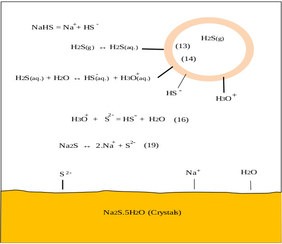
On the other hand, the oxygen in the air reacts with NaHS and Na2S to give undesired products such as Na2CO3, Na2S2, Na2S2O3, and Na2SO4, this is observed in the pulp and paper industry [38]. CO2 and O2 come from the air, these can enter the reactor through the phosphorus pentasulfide feed system or through the reactor seals. During the industrial process the control of these gases is achieved by making a vacuum in the ADTF reactor. Fig. (1) shows the proposed mechanism where the presence of the three phases is observed as well as the species involved in the formation of sodium sulfhydrate. It shows the summary of the chemical processes that during the absorption of H2S in a solution of sodium sulfhydrate saturated with sodium sulfide, where the presence of the three phases is observed. The mechanism presented is an extension of the Al-Tarazi model [39] of a liquid gas contactor for formation of crystal and aggregates.
 |
(21) |
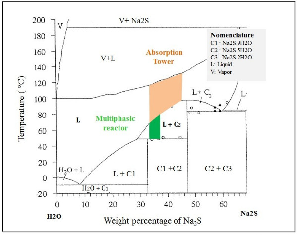
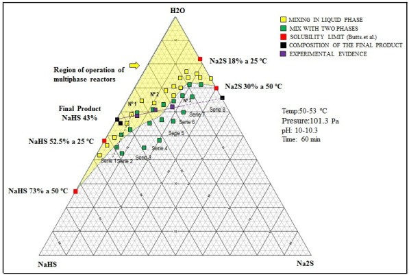
The hydrolysis of NaHS can also occur to form H2S, and can be appreciable and sensitive to small variations of pH of neutral aqueous solutions [40]. Multiphase reactors are widely used in chemical industries because they offer high flexibility and allow appropriate conditions according to the requirements of the chemical reaction [41]. To maintain the phases in contact, an efficient system [42] of agitation is necessary, which allows keeping balanced the amounts of the different substances in each phase [43, 44]. The wide range of agitation devices (and the variety of impellers) and geometric parameters of the system allows to select a precise combination for the intended application [41]. In these types of reactors, under the action of the impeller or liquid agitation device, it allows the suspension of solids [42] and the dispersion of the gas phase (entering through the bottom of the container and close to the impeller), in such a way that the contact between the three phases is favored [45]. According to the phase diagram (see Fig. 2) of the Na2S-H2 system, if the reactor will be worked in a system formed only by sodium sulfide and water, it can be seen that we have two regions where two phases are present, such as L + C1 and L + C2.
The objective of this research was to study the manufacture of sulphides, specifically sodium sulphides, in an isothermal multiphase chemical reactor to produce concentrated aqueous solutions of sodium sulfhydrate greater than 40% (NAHS 42-45%) from chemical reactions in a Ternary Gas-Liquid-Solid system, recovering the hydrogen sulfide (H2S) generated during the industrial production of dithiophosphoric acids.
For which we propose to develop a more attractive process by reducing the temperature of the process with respect to the technologies currently used in this area.
2. MATERIALS AND METHODS
2.1. H2S and ADTF Production
Before indicating the characteristics of the reactor for this study, first we give the general guidelines of how hydrogen sulfide is generated in the Reactivos Nacionales S.A Company, which is the main problem we are trying to solve. The production of dithiophosphoric acids (ADTF) is carried out in a stirred tank-type semicontinuous reactor, where the phosphorus pentasulfide and a specific alcohol mentioned above are reacted. On alcohol at 90 ° C, the phosphorus pentasulfide is added, the chemical reaction produces the ADTF and H2S. The reactor is maintained at a pressure of -20 mmH2O (-196.14Pa), and a production batch takes 6 hours. Table 1 shows the production of H2S depending on the alcohol used. The raw materials are industrial grade at 99% and theoretically generate 92 kg H2S for each production batch, according to the production record of ADTF and the balance of material are recovered 90.4 kg H2S, are recovered, which represents 98.3% recovery of the theoretic value. The H2S (g) for its treatment is bubbled in a stirred tank with a dilute solution of Na2S-NaOH or sent to the scrubber where diluted solutions of sodium sulphide are obtained with a concentration by 20 to 25% weight. Faced with this problem, a technological alternative is sought that allows to dispose the residual H2S in such a way that it improves the economy of the main process.
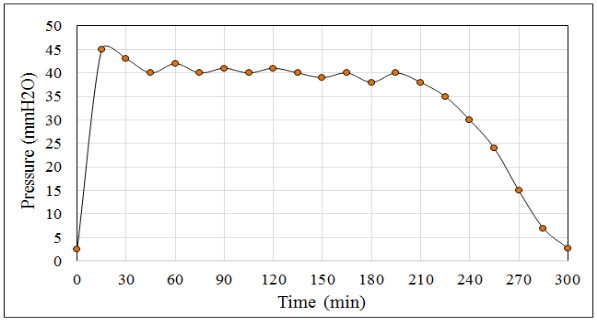
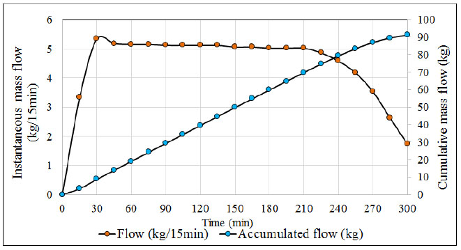
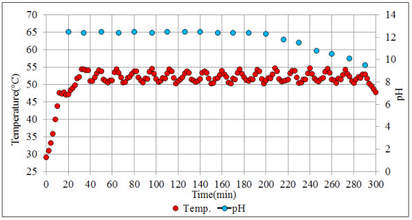
When monitoring the values recorded by the pressure transmitter it is common to find the following pressure patterns (see Fig. 3), H2S flow (see Fig. 4) and the temperature and pH profiles (see Fig. 5) during the ADTF production process.
| Products | Alcohol (kg) | P4S10(s) (kg) | ADFT (kg) | H2S (kg) |
|---|---|---|---|---|
| ADTF from isopropanol alcohol | 648.8 | 600 | 1156.8 | 92 |
| ADTF from isobutanol alcohol | 800.3 | 600 | 1308.3 | 92 |
| ADTF from isopentanol alcohol | 951.8 | 600 | 1459.8 | 92 |
2.2. Specification of H2S Flow
The ADTF production plant has a flowmeter at the outlet of the condensers where the gas output is monitored at room temperature (22° C) throughout the reaction process. Figs. (4 and 5) show, the H2S flow pattern and temperature profile in the industrial reactor during ADTF production. The mass flow is calculated with the following equation:
 |
(22) |
The operating parameters of the flowmeter are specified taking into account the following: Kf: flowmeter constant 0.045 m2 (22 ° C, 101.325 kPa). ΔP: mmH2O ρ(H2S): (1.42 kg.m-3, 21.1 ° C and 101.325 kPa) or (1.220 kg.m-3, 21.1 ° C and 101.325 kPa).
2.3. Characteristics of the Stirred Tank Reactor: Batch Mode Experimental
The configuration of the stirred tank pilot reactor used for this study is shown in Fig. (6). The main parts that make up the pilot reactor are: (1) a reactor with variable agitation; (2) a pH meter; (3) A temperature meter; (4) an H2S analyzer; (5) heating and cooling medium. Very close to our system is the industrial semicontinuous reactor for the production of ADTF, where H2S is produced, which was conveniently used for experimental development. The reactor planned for this study operates at temperatures lower than the temperatures of recovery technologies by absorption towers (less than 70 oC) in order to facilitate the H2S absorption in the reaction medium.
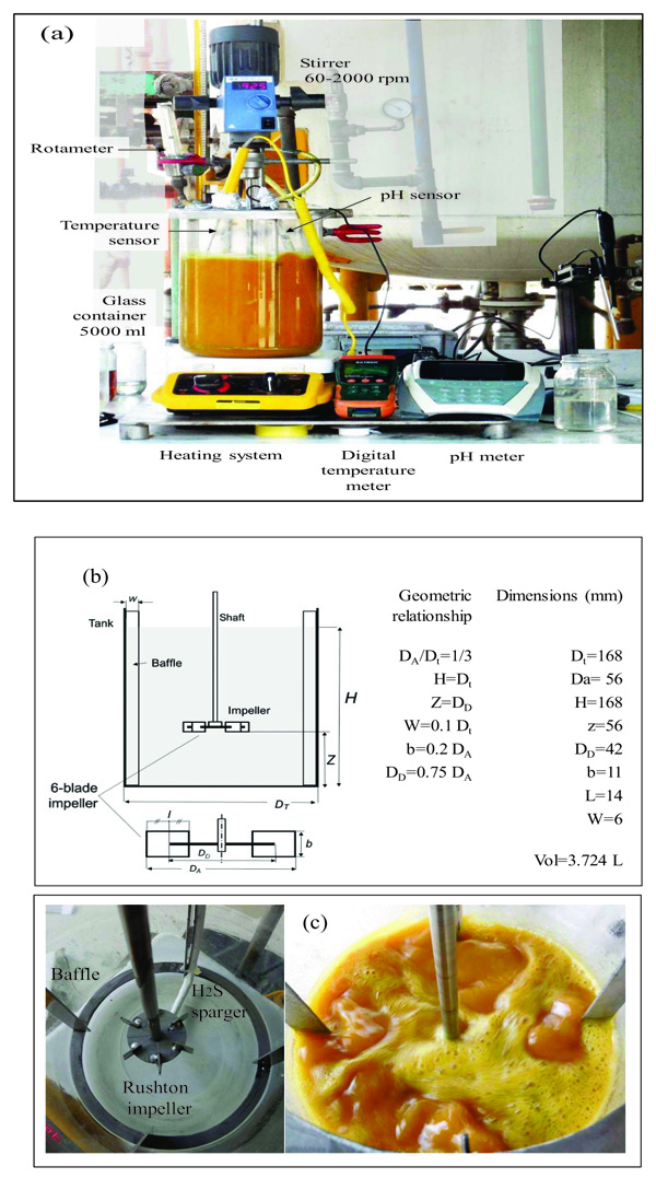
For the experimental development, a cylindrical glass vessel of 168 mm internal diameter and 210 mm in height was used, with a liquid level equal to the tank diameter, with a total volume of 5 L. The agitation system described by [46], was applied to design the components of the stirred tank, such as the impeller and deflectors (Fig. 6). Similar geometric relationships (Fig. 6b) are also shown in [47, 48] ; [49, 50, 51]. With this configuration there is available a reaction volume of 3.72 liters sufficient for the end pursued. The composition of the reaction mixture is Na2S (13%), NaHS (27%) and H2O (60%) with an average density of 1.26 g / l at 50 oC. The reactor can treat 4650 g of reaction mixture with a final volume of 3.910 liters, which is equivalent to approximately 5000 g of NaHS when the final product is formed. Fig. (6) shows the detailed dimensions of the reactor used for the experiments. The rotameter was calibrated for a water column of 218 mm H2O with flow rates ranging from 0.1 vvmin (at 25 oC) to 0.8 vvm (at 25 oC). Take into account that vvmin represents the volume of gas per volume of the reaction medium per minute. Taking into account that the volume of the medium is 3.8 liters of biphasic mixture (composed of crystals of sodium sulfide and aqueous solution of NaHS) we have: (0.8 liters H2S/min = 0.21 vvmin, 1.6 liters H2S/min =0.42 vvmin, liters H2S/min = 0,85 vvmin). To measure the presence of H2S that could escape from the reactor, a gas detector has been used (Brand: Aeroqual, Model: Series - 200, Sensor: EHT / EHT2 range: 0 - 100ppm, peaks up to 300ppm). The device is a precise meter for the measurement of H2S concentrations in the air or in gas streams. The gas detector has a built-in pump in the head that sucks gases from the reactor to be analyzed. When there is a high presence of H2S in the pilot reactor, a large amount of foams will be observed on the reaction medium. So in these circumstances the gas sensor should be disconnected to avoid saturation of the catalytic sensor.
3. RESULTS AND DISCUSSION
3.1. Determination of the Bubble Diameter of H2S
The bubble size cannot be determined by mathematical models for this type of reactors, because the system is a complex mixture, that is why we have proceeded to measure directly by photographic captures using the microscope (UNIMAKE, USB Digital Microscope 1000X) to determine the size of the bubbles closest to the surface of the reactor.
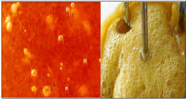
The photographic capture (Digital Camera, Nikon Coolpix S6500) was made stopping untimely agitation and gas entering the reactor. The measurement must be fast because the bubbles reduce their size since they are absorbed in the aqueous solution or they abandon the reaction medium. A uniform distribution of the bubbles in the liquid is observed and it can be inferred that the bubbles have diameters of less than 300 μm measured at a reaction temperature of 53°C, stirring speed of 700 rpm and a flow of H2S 0.4 vvmin. The bubbles were (Fig. 7a) (A= 300µm, B= 80μm, C= 60µm). The bubbles are of H2S and it occurs quite frequently when the reaction solution is almost saturated with H2S and when NaHS is already formed in its entirety (the pH of the reaction mixture is around 8). On the other hand, when air enters the system, O2 becomes thiosulphate and collapses, and if there are bubbles, it is due to Nitrogen (N2). The vacuum pressure prevents the entry of air, the gas flow meter does not show the passage of any gas, and if CO2 has passed must be negligible because the content of thiosulphate is minimal and almost always maintained at values of 100 mg /L, and has no impact on the specification of the final product. Fig. (7b) shows the multiphase reactor in operation, the foam that is formed when the flow rate of H2S (g) is much greater than 0.8 vvmin is observed. This foam mattress arrives until the empty space of the reactor is reached. In other research work [52], the photographic method was used for this purpose, where the bubble diameters were evaluated for selected bubbles in different locations at different times. The foam formed from sodium sulfide crystals Na2S5H2O, when cooled, crystallizes and adheres to the walls of the reactor generating various problems such as the impediment of the flow of H2S. The hydration temperature of Na2S is 73°C [28], and the dehydration temperature is 80 °C (Eq. 11) [24, 53], which represents a process of hysterisis. Mechanically, stirred tank reactors in which the gas phase is dispersed by means of a dispenser and/or a stirrer are used in many chemical processes (gas absorption etc) [54]. Stirred vessels are very commonly used for gas–liquid reactions on account of their flexibility and good performance for mass and heat transfer [55]. When a single phase is present, the fluid flow induced by the impellers is relatively easy to predict. The addition of a second phase to the reactor increases the hydrodynamic system complexity [54, 56]. Gas flow pattern is important. It controls the degree of recirculation and backmixing of the gas phase, which in turn determines the mean concentration driving force for mass transfer. In the homogeneous regime in an agitated vessel, the superficial gas velocity, vS < 0.02 to 0.03 m/s, and the bubbles have a monomodal size distribution with a small mean size, generally between 0.5 and 4 mm. Here, the impeller controls the flow pattern and bubble size [55]. Good mass transfer performance requires large interface area between gas and liquid (resulting directly from small bubble size and high gas fraction, given the fixed gas rate), and a high mass transfer coefficient (associated with local levels of turbulence) [55].
3.2. Formation of Na2S.5H2O Crystals at 50-55 ° C
It is important to bear in mind that the formation of Na2S.9H2O crystals occurs in a temperature range of 30 to 35 ° C, with a low content of Na2S.5H2O.The reaction parameters for the transformation of sodium sulfide crystals in the pilot reactor were the following: Stirring speed: 700 rpm; initial temperature: 26oC, maximum reaction temperature: 30oC, stirring time 30 minutes. The can be explained taking into account (Eq. 2), in addition to:
| Na2S + 9 H2O ↔ Na2S.9H2O (s) | (23) |
| Na2S + 5 H2O ↔ Na2S.5H2O (s) | (24) |
When the temperature of material is lower than its melting point, crystalline hydrate will wholly or partially strip its water of crystallization. When the temperature decreases, Na2S(s) adsorbs water and transforms into Na2S.nH2O(s). Under many circumstances, such hydration heat could be much higher than dissolution heat [57]. A curve showing the solubility of hydrates of Na2S can be consulted in [58]. If crystallization with agitation takes place much longer (48 hours) and with temperatures of 25°C, most of the Na2S.5H2O will have been transformed into Na2S.9H2O crystals with particle size that will be around 4mm. Working at low temperatures with a high concentration of crystals (Fig. 8) causes suspension problems in the reaction mixture, blockage of the bubbler holes and makes it difficult to react the reaction mixture with H2S for the conversion of Na2S to NaHS. With formulation of Table 2 and reaction conditions (stirring speed: 700 rpm; initial temperature: 26 oC; maximum reaction temperature: 50 oC; and stirring time: 30 minutes), mainly Na2S.5H2O crystals are formed according to Eqs 2 and 3.
| Components | Quantify |
|---|---|
| NaHS (43%) | 3964 g |
| [NaHS] | 43.20% |
| [Na2S] | 0.20% |
| H2O | 110 g |
| NaOH (50%) | 638 g |
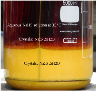
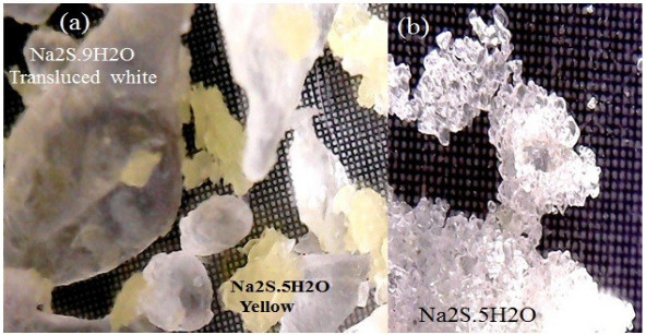
With formulation of Table 2 and reaction conditions (stirring speed: 700 rpm; initial temperature: 26oC; maximum reaction temperature: 50oC; and stirring time: 30 minutes), mainly crystals of Na2S.5H2O are formed which explains by Eqs 2 and 3. When the aqueous sodium hydroxide is contacted with the sodium sulfhydrate solution, the conversion to sodium sulfide crystals immediately occurs. The reaction is exothermic and instantaneous, and in less than 1 minute the NaHS is transformed into Na2S, the reaction mixture raises its temperature to 48 oC. The amount of crystals obtained is 1047 g, which represents 22% according to the weight of the mixture. The crystals show particle diameters less than 1500 mm. The shape and distribution of the crystals is more homogeneous when the temperature is maintained in a range of 50 °C to 55 °C. Dehydration of Na2S.9H2O changes to a yellow color [25], indicating the presence of Na2S5 H2O, this effect is shown in Fig. (9).
3.3. Influence of the Solid Content of the Reactioning Mixture in the Progression of the Reaction
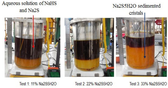
To confirm that the reaction mixture with a solids concentration of 22% (Na2S5H2O) has good reaction properties as opposed to solids concentrations of less than or greater than 22%, three tests were organized where each reaction mixture (NaOH and NaHS) form crystals of sodium sulphide (Na2S.5H2O) (see Table 3) and finally react with hydrogen sulphide to give 43% NaHS. The amounts of NaHS used include stoichiometric amounts which will react with the sodium hydroxide and those which keep the crystals formed in suspension. The amounts of water used in the formulations allow to correct the final concentration of the product. The formulations used make it possible to initiate the reaction with the H2S with a volume of reaction mixture of 3578 mL corresponding to the volume of reactor established to maintain the configuration of the reactor which is also object of analysis. The conditions of these tests were: reaction temperature (50-55°C); agitation (impeller: 700 rpm); reaction time (2.25 hrs); and H2S flow (0.41 vvmin). When the reaction mixtures were prepared with NaOH and NaHS, the stirring was stopped for 30 minutes so that the Na2S5H2O crystals formed sedimented while maintaining the reaction temperature at 50°C. Fig. (10) shows the presence of solids (Na2S5H2O) in each case.
The presence of solid particles causes different results in gas-liquid and gas-liquid-solid systems. In gas-liquid systems, a higher agitation speed can effectively break bubbles into smaller ones and hinder the bubble coalescence. But this capacity is weakened when solid particles are introduced into the system because the particles reduce the velocity of fluid flow and may collide with bubbles [59]. For very fine particles (< 10 µm) at low solids concentration (< 0.6% v/v) and very large particles (> 2000 µm) at high solids concentration (> 10% v/v), the trend is an increase in the gas holdup [60, 61]. Gas-liquid-solid three-phase mechanically stirred tank reactors are widely applied in many industrial processes [59], where particles suspension are influenced in a complex manner by gassing [55]. When solid particles are added in gas-liquid systems, the better understanding of solid suspension and mass transfer is important to the design and scale-up of gas-liquid-solid stirred tank reactors [59, 62, 63].
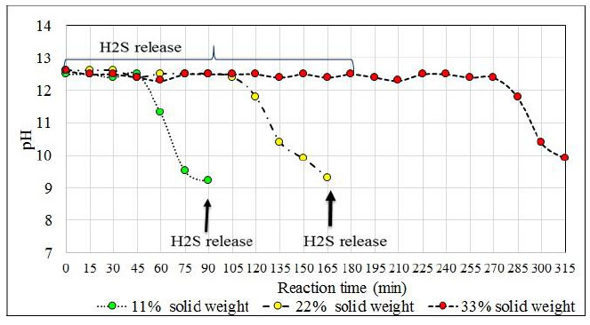
Reaction mixtures Test 1, 2 and 3 are located within the biphasic region and the concentrations of the species will be displaced until 43% sodium sulfhydrate solutions are obtained. Fig. (11) shows the location of these points (No 1, 2, and 3). The shaded region shows the different ternary mixtures with good agitation properties. The reaction mixtures are reacted with the hydrogen sulfide with a gas flow rate of 0.41 vvmin and the progress profile of the reaction is shown in Fig. (11). The reaction mixtures with 11, 22 and 33% solids are reacted with the hydrogen sulfide with a gas flow rate of 0.41 vvmin and the progress profile of the reaction is shown in Fig. (12).
| Reagents | Test 1 | Test 2 | Test 3 |
|---|---|---|---|
| NaHS, 43% | 4341 g | 3964 g | 3585 g |
| [NaHS] | 43.40% | 43.40% | 43.40% |
| [Na2S] | 0.33% | 0.33% | 0.33% |
| [Na2CO3] | <0.1% | <0.1% | <0.1% |
| H2O | 60 g | 121 g | 181 g |
| Reagents | |||
| NaOH 50% | 319 g | 538 g | 957 g |
| H2S ( 0.4 vvmin) | 137 g | 275 g | 412 g |
| NaHS, 43%/ NaOH, 50% | 13.6 | 6.21 | 3.74 |
| Mass balance | |||
| [Na2S], % | 6.89 | 13.46 | 20.02 |
| [NaHS], % | 35.14 | 26.95 | 18.74 |
| [H2O], % | 57.9 | 59.59 | 53.84 |
| Crystals weight | 512 g (10.8%) | 1047 g (22.16%) | 1586 g (33.5%) |
| Liquid weight | 4208 g | 3676 g | 3137 g |
| Total weight | 4720g | 4723 g | 4723 g |
| Solid phase volume | 1052 mL (29%) | 1473 mL (41%) | 2526 mL (70%) |
| Liquid phase volume | 2525 mL | 2105 mL | 1053 mL |
| Total volume | 3577 mL | 3578 mL | 3579 mL |
3.4. Influence of Temperature on the Absorption of H2S
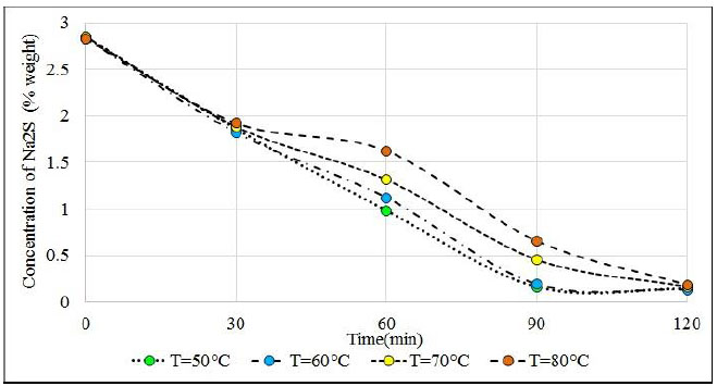
One of the most discussed topics in the treatment of H2S is the low solubility of it in concentrated solutions of sodium sulfhydrate and sodium sulfide. To this end, four tests were organized at 50, 60, 70, and 80°C in reaction solutions with an approximate of 40.5% NaHS and 2.8% Na2S. The volume of the solution was 3 725 ml; the flow of H2S was 0.12 vvmin ((0.44 L.min-1) at 25 oC); and the impeller speed 700 rpm. The reaction solution under study at 50 °C does not have sodium crystals that disturb the absorption results. Once the sodium hydroxide is added, it is necessary to cool the solution, then heat the solution to the test temperature; then proceed to bubble the H2S. Table 4 shows the results of these tests. At 50 oC an acceptable absorption time is obtained and there is almost no presence of Na2S.9H2O crystals that affect the suspension and dispersion of gases in the reactor. The solid phase of the reactor is composed almost entirely of Na2S.5H2O and a good absorption of H2S is obtained in the reaction mixture. The choice of 50 oC is more due to the absorption capacity of H2S with adequate agitation.
The reactant solutions started from the same concentration value of sodium sulfide and sodium sulfhydrate around 2.85% Na2S; 40.58% NaHS and 56.57% H2O. After 60 minutes of H2S bubbling, Na2S reactants whose temperatures are 50°C and 60°C which are very close to the value of 1%, while solutions of 70°C and 80°C are very far from this value (see Fig. 13) were observed.
At 90 minutes, the reactants that are at temperatures of 50°C and 60°C have reached equilibrium with concentrations close to 0.15% and remain at this value until 120 minutes, while solutions that are at 70°C and 80°C continue to fluctuate around 0.4%. These solutions reach equilibrium at 120 minutes with approximately 0.15% Na2S. It is clearly observed that hot solutions greater than 70°C have a delay in the progress of the reaction, as a result of the decrease in the solubility of H2S in hot solutions, other works also indicate the decrease in solubility with the increase in temperature in absorption towers [64]. The solubility minimum occurs at higher temperatures. The reasons for these related phenomena are not fully understood, but derive to a large extent from the changes in water structure (breakdown of hydrogen bonding) that take place at increasing temperatures [65]. Up to 30 minutes, the samples of the four tests have almost the same content of Na2S approximately 1.8%. This means that the sodium sulphide in the reactant solution allows the absorption of H2S and when the Na2S content decays, the solubility of the H2S also decays. It is observed that the reactants have absorbed on average 51.8 grams of H2S and according to the content of Na2S it was expected to capture an approximate amount of 57.4 grams of H2S. Therefore, almost 90% of the H2S that has been bubbled was absorbed.
| Reactants | Temperature | |||
|---|---|---|---|---|
| 50 oC | 60 oC | 70 oC | 80 oC | |
| Preparation of the Reactioning Mixture | ||||
| NaHS 43.6% | 4 536 g | 4 536 g | 4 536 g | 4 536 g |
| [NaHS] | 43.6% | 43.6% | 43.6% | 43.6% |
| [Na2S] | 0.32% | 0.32% | 0.32% | 0.32% |
| Reactants | ||||
| NaOH 50% | 120 g | 120g | 120g | 120g |
| Balance of materials | ||||
| [Na2S] | 2.85% | 2.83% | 2.85% | 2.83% |
| [NaHS] | 40.58% | 40.43% | 40.58% | 40.53% |
| [H2O] | 56.57% | 56.74% | 56.57% | 56.74% |
| Weight of the reactant solution. | 4 654 g | 4 653 g | 4 658 g | 4 657 g |
| H2S | 57.4 g | 57.4 g | 57.4 g | 57.4 g |
| Results | ||||
| Final weight reaction.solution | 4 706 g | 4 707 g | 4 713 g | 4 710 g |
| Amount H2S absorbed | 51 g | 53 g | 52 g | 51 g |
| Balance de materiales-calculado | ||||
| [Na2S] | 0.14% | 0.13% | 0.16% | 0.18% |
| [NaHS] | 43.95% | 43.79% | 43.66% | 43.41% |
| [H2O] | 55.91% | 56.05% | 55.56% | 56.07% |
| Test No 1 | Test No 2 | Test No 3 | |
|---|---|---|---|
| Mean temperature | 30 oC | 50 oC | 70 oC |
| Presence of H2S | Yes (Until 45 minute- 125 ppm) | Yes (from minute 150, 85 ppm) | Yes (from minute 135, 95 ppm) |
| Total, NaHS 43% | 4 952 g | 4 977 g | 4 967 g |
| [NaHS] | 43,75% | 43,27% | 41,83% |
| [Na2S] | 0,21% | 0,15% | 1,76% |
| [H2S] | 56,34% | 56,58% | 56,41% |
3.5. Influence of Temperature in the Advance of the Reaction
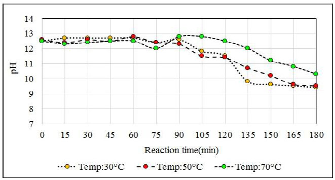
The influence of temperature on the reaction for the proposed formulation (13.3% Na2S, 26.9% NaHS and 59.8% H2O) was studied (Table 5). This reaction medium allows the sodium sulfide crystals to remain in suspension when appropriate agitation is applied. In addition to sodium sulfide, ions react with the absorbed H2S in the middle. After 180 minutes of reaction, the reaction solution shows crystals of sodium sulphide, and in a higher proportion when the reaction mixture is at 30°C. After 10 minutes of settling, a reactant solution is observed whereby practically 50% of the reactor volume consists of sodium sulfide crystals. This level of solids in the reactor is unfavorable and affects the agitation as well as in the conversion process.
The reactions at 30°C and 50°C end before the reactions at 70°C end because at lower temperatures the reaction solution absorbs more H2S. This effect was expected since at temperatures close to 70°C H2S solubility is lower than at the previous ones. According to the chemical analysis of the product obtained at the temperature of 70°C, it is observed that it had not exceeded the required concentration (greater than 43%), and the analyzer of H2S from minute 150 registered high values of H2S that left the reactor (95 ppm H2S). A generation of NaHS of 1 023 g (i.e. 4 990 g NaHS in the reactor) was expected. However, 4967 g of NaHS was obtained in the reactor. That is, a difference in weight of 23 g which means that about 8% of the initially planned H2S (275 g) had not been absorbed. On the other hand, the reaction at 30°C releases H2S from the reactor from the start of bubbling and the release continues until 60 minutes later, after which the load becomes lighter and the H2S level escaping from the reactor slowly decreases. From the agitation point of view, the high presence of solids in the reaction mixture that is at 30°C causes the crystals to deposit in the deflectors of the reactor and vary the final concentration of the obtained product.
Working at temperatures of 30°C according to the proposed formulation, problems at the beginning of the reaction due to the adherence of the sodium sulfide crystals on the surface of the reactor that affect the correct agitation of the medium because at this temperature there is a high load of sodium sulfide crystals that represent about 52% according to the volume of the reactor that affects H2S absorption. The most favorable test is at 50°C because no significant amounts of H2S are detected at the beginning of the reaction, but until minute 150 which is where practically all the Na2S has reacted and no more H2S is absorbed. At a temperature of 50°C, the amount obtained differs from what is expected by 11 g. In Fig. (14) the pH profile is observed with respect to each reactor temperature and the delay in the completion of the reaction when tested at 70oC is clearly seen.
This work was carried out in the Reactivos Nacionales S.A, in order to solve a serious environmental problem related to hydrogen sulfide produced as a byproduct in the production process of dithiophosphoric acids. The problem was solved by producing NaHS, which the company can commercialize. Next we show the dimensioning of the industrial reactor.
3.6. Chemical-industrial Reactor Design
The stirred tank reactor is the most frequently used in process industries [66] to bring about an excellent solid-liquid, gas-liquid or gas-solid-liquid contact. The adequate degree of suspension of solid particles mean homogenization of slurry so formed or a near homogenization such that the suspension ensures uniform process conditions leading to predictable results. And the adequate degree of mixing is the required degree of turbulence which minimizes the mas transfer resistances [67]. For the industrial manufacture of sodium sulfhydrate in aqueous solution, the three-phase reactor has the following functions:
- To ensure the adequate contact of the reactants to obtain NaHS: H2S(gas) - sodium sulfide crystals(solid) - reaction solution (liquid).
- To provide sufficient contact time between substances.
- To allow temperature conditions and composition of the reactants so that the chemical reaction develops at the desired speed.
The hydrodynamics of the fluids and the geometrical configuration of the reactors are key to understanding the mixing phenomena. The geometric configuration is so important that the processes can be considered of specific geometry. The turbine of discs with six flat blades for the systems of agitation with radial flow was developed from the studies of Rushton and is considered like a geometric configuration of reference [68]. For that reason, this configuration has been used for the present study. The 6-blade Rushton disc turbine was shown to be the best impeller over a wide range of gas flow rates for dispersing both solids and gases simultaneously [69].
3.6.1. Dimensioning the Sparger
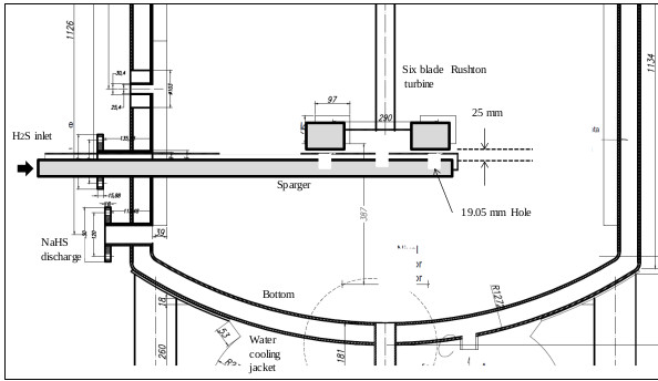
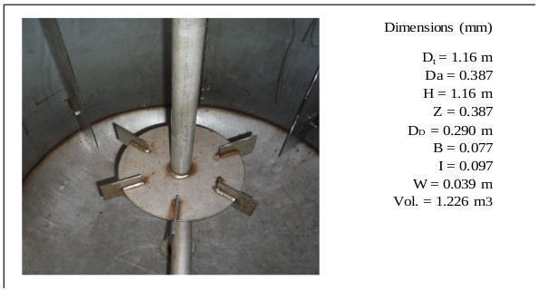
The sparger is an important element of the reactor. Its design should allow easy cleaning of the device. Inside the sparger, sodium sulfide crystals are deposited from the reaction mixture when the H2S gas does not enter the reactor. Fig. (15) shows the cross section of the lower part of the reactor, where the agitator is installed, and (Fig. 16) shows the dimensions and capacity of the industrial reactor, based on the correlations shown in Fig. (6c) [42, 46], as well as the Rushton turbine of stainless steel. If it becomes clogged, it must be cleaned on the outside with a stream of hot water to dissolve the crystals inside. The sparger provided for this application consists of a straight tube of 1 ½ “diameter Schedule 40, the material is made of AISI 316 stainless steel. The sparger is provided with three holes of 0.75 inches of diameter, through sparger the H2S bubbles are discharged near the impeller. The location of the sparger is important and is related to the interfacial area (bubble size). In the design of the reactor, the sparger has been placed in favor of flow current for both pilot and industrial tests. The main problem that arises in the design of gas-liquid reactors is the correct evaluation of the interfacial area, a magnitude for which there are no general methods of estimation and which suppose the greatest difficulty in scale changes. Most researchers have found that the specific interfacial area in a bubbling tank is related to gas surface velocity and the power supplied to the dispersion (per unit volume). Molina and collaborators analyze the influence of the variables of operation in the region of low intensities of agitation, on the interfacial area in cylindrical tanks where the disposition of the sparger is modified so that the gas bubbles in favor and against the flow currents [70].
3.6.2. Reactor Temperature Control System
The objective of controlling the temperature in the reactor is to achieve an adequate conversion in the formation of the product and to keep the system operating around the specified conditions. Two stages take place in the reactor:
- Product training
- Heat removal from the reactor through the cooling jacket
The reagent (H2S) entering the reaction with sodium sulfide generates heat and heats the system. Temperature is the variable to control, although the most important for the production of NaHS is to control the concentration of the species that are formed in the reactor.
A strict control of the minimum temperature (50oC) of the NaHS reactor is essential to avoid the formation of Na2S.9H2O crystals that can cause problems. Controlling the temperature below 55oC will allow maintaining a good solubility of the H2S in the reaction solution and thus avoid losses of H2S outside the reactor.
3.6.2.1. Thermostat
The temperature controller is an electronic device that receives the signal from the sensor, and transforms it into temperature values according to the algorithms established for each type of sensor. The controller sends an electrical signal to the final control element (water valve) when comparing the value of the process with the control value using the control mode set. The driver used is of the brand Autonics, Model TZ4M. The type of control that can be done with this device are ON-OFF, P, PI, PD, PIDF and PIDS. For our case, the ON-OFF basic mode was used (Fig. 17).
3.6.2.2. Temperature Sensor
The temperature sensor installed in the reactor is a three-wire Pt100 sensor, whose measuring range ranges from -100 oC to 200 oC, 6” bulb length, ¼” bulb diameter, aluminum head.
3.6.2.3. Control Valve
The control valve used is a full-pass valve with a diameter of 1 “, sufficient for the passage of cooling water with a maximum flow of 6.02 m3 / h.
3.6.2.4. Control Mode
The ON-OFF mode is the one used for the temperature control of the reactor, this control is the most basic and efficient enough for our purpose. The equipment of the TZ4M controller of the AUTONICS brand is configured in such a way that:
- It turns on when PV (process value) is less than SV (control value) (53 oC)
- It turn off when PV is greater than SV (53 oC).
3.6.3. Balance and Stoichiometry of the Reaction: Industrial Essay
As in the pilot tests, for the industrial tests, it has been determined that the reaction medium will be formed initially of 43% sodium sulfhydrate concentrated solutions (liquid solution at temperatures higher than 20 oC). In this medium, the sodium sulfide (Na2S.5H2O) crystals will form when stoichiometric amounts of NaHS and NaOH react. According to preliminary work at the pilot level it has been confirmed that one of the best proportions (of sodium sulfide, sodium sulfhydrate, and water) in the reaction mixture should start from a weight ratio of 43% NaHS / 50% NaOH = 6.24 and a reaction mixture of overall percentage composition as follows: 13.3% Na2S, 26.9% NaHS and 59.8% H2O. All the industrial tests will be carried out starting with a 50% sodium hydroxide industrial grade and sodium sulfhydrate greater than 43% (with contents less than 0.4% Na2S) in the commercial grade that is available at the plant.
For the purposes of this calculation, the NaHS available for the first test has a concentration of 43.2% (with contents less than 0.1% of Na2S). Formation of Na2S, taking into account (Eq. 7), starting with 212 kg of 50% NaOH. This equation allows to determine the requirements of reactants and reaction media for the formation of sodium sulfide. NaHS requirement at 43% for the formation of Na2S:
 |
MNaHS = 148.6 kg, M H2O = 195.0 kg (water that accompanies sodium sulfhydrate), MNa2S = 0.3 kg (Sodium sulphide that accompanies sodium sulfhydrate): MNaHS, 43,2% = 343.9 kg
Na2S generation:
 |
H2O generation:
 |
Water from 50% sodium hydroxide (considering that the content of carbonates and other substances are less than 0.1%) is: M H2O = 106 kg (of sodium hydroxide).
NaHS Requirement 43.2% as Reactant and Reactant Medium
The requirement of NaHS at 43.2% as reactant and reactant means is 1 322 kg of NaHS 43.2% of which 978.9 kg, will serve as a reaction medium that will promote the suspension of the sodium sulfide crystals formed. In 978.9 kg of NaHS 43.2% it has as: NaHS = 422.9 kg, Na2S = 1 kg and H2O = 555 kg.
Adjustment of the Reaction Mixture
Soft water is added for the NaHS dilution in order to correct the NaHS concentration to 43.5%.The water for the compensation and readjustment of the concentration of the reaction mixture is: M H2O = 34 kg
The sum of all the contributions and the chemical species present in the reaction mixture corresponding to the sodium sulfide formation step makes a total of 1568.9 kg for a reactant solution with the following weight percentage composition: MNa2S = 208.2 kg (13.27%), MNaHS = 422.9 kg (26.95%), MH2O = 937.8 kg (59.78%), M total = 1 569 kg (100%). It has experimentally been verified that under this formulation and at 50 °C, about 40% by volume of solids formed by sodium sulfide crystals and 60% of a liquid phase are obtained. The mixture possesses good properties for agitation. The content of solids (sodium sulfide crystals) at 50 °C is 22.16% by weight. Weight of the solid phase: 347 kg, Weight liquid phase: 1 220 kg.
Initial composition of the chemical species in aqueous phase (reactant solution) at 50 oC is: 3.6% Na2S, 35.0% NaHS, 61.0% H2O.
Generation of NaHS: According to (Eq.8)
For the conversion of all the sodium sulfide content of the reaction mixture the amount of H2S required is:
 |
MNaHS = 299.1 kg of which 149.5 kg is generated as final product and the rest is reincorporated into the reaction medium (NaHS 43%): MNaHS = 149.5 kg. From the total balance of the reaction mixture and finishing the reaction there is a total mass of: M total = 1 659.8 kg
3.7. Determination of Critical Speed (NJS) for the Suspension of Na2S Crystals in a NaHS Solution for the Pilot Reactor and Industrial Reactor
Solids suspension applications require accurate specification of the impeller speed because these operations are power intensive. These stirred tanks are usually operated at the just suspended speed, Njs, which is the impeller speed at which no particles remain stationary at the bottom of the tank for more than 1 or 2 s [71-76], and five states of suspension were observed that occur in solid liquid agitation with respect to the speed of the agitator (N). When the agitator speed reaches the Njs it can be said that a complete suspension is found [77]. The critical impeller speed for solids suspension (Njs), also has been studied in gas inducing mechanically agitated contactors fitted with two impellers by Saravanan et al., the study shows various stages of the solid phase during the process of solid suspension [78]. A critical analysis of this correlation (Eq. 25) can be consulted in [72]. The geometric parameters that affect Njs are impeller diameter, tank diameter, off-bottom clearance of the impeller, type of impeller, off-bottom clearance of baffles and shape of the tank bottom [72, 79]. S is a function of impeller type, impeller diameter and off-bottom clearance [72]. S is very sensitive to geometry [72], but also depends on the type of the particle [72, 80]. The amount of suspend solids as a function of impeller speed depends on the presence of fine particles in the suspended material. The more fines are present, the higher the amount of suspended solids are result [81]. For the design of the critical speed of suspension of the industrial reactor it is necessary to know the correlation constant of Zwieteering (S), which is visually characterized [73]. For this, the characteristics of the suspension in the pilot reactor were observed considering (Eq. 25).
 |
(25) |
For the reaction mixture (see 3.5): ν= 0.00488 m2/s (NaHS kinematic viscosity 43% at 50 °C), g= 9.806 m/s2 (Gravity), ρl= 1.28 kg/m3 (NaHS density 43% at 50 oC), ρs= 1.58 kg/m3 (Density of solid Na2S.5H2O), X= 0.22 concentration of solids (weight ratio), dp =1500 μm (particle diameter), D = 0.056 m (agitator diameter). With the pilot reactor, different speeds have been tested and it has been concluded that for a speed of 600 rpm (10 rev / s) an adequate suspension of the crystals is achieved.
The vortex on the agitation surface and the distribution of particles is not appreciated in the solution. It is homogeneous, even from 550 rpm. While 600 rpm (10 rev / s) is the critical suspension rate (Njs) in the multiphase reactor, the correlation constant “S” has a value of 4.516. The critical velocity for the solids suspension (Njsg) in the Gas-Liquid-Solid reactor is calculated according to (Eq. 26) [82].
 |
(26) |
Constant k was determined by [83] whose value is 0.94. Where: Njs = 10 rev / s (Critical speed for the dispersion of gases in an S-L reactor) and Qg = 0.41 vvm (gas flow). Applying (Eq. 26), the minimum value for Njsg is 623.12 rpm (10.39 rev / s). For the industrial reactor, the critical speed (Njs) for the suspension of Na2S crystals in a NaHS solution is evaluated taking into account: S = 4.516, D = 0.387 m (diameter of the agitator), and the other parameters of the (Eq. 25) are the same as mentioned above: it is 58.06 rpm (0.967 rev / sec). For an aeration rate of 0.2 vvm and with Eq. 26, the minimum critical velocity (Njsg) for the suspension of solids in the industrial reactor results in 69.34 rpm (1.16 rev / sec). Finally, the conditions for NaHS production at the industrial level are established as follows: Composition mentioned above, temperature of 50°C, agitation speed of 80 rpm, and a luxury of
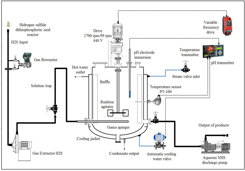
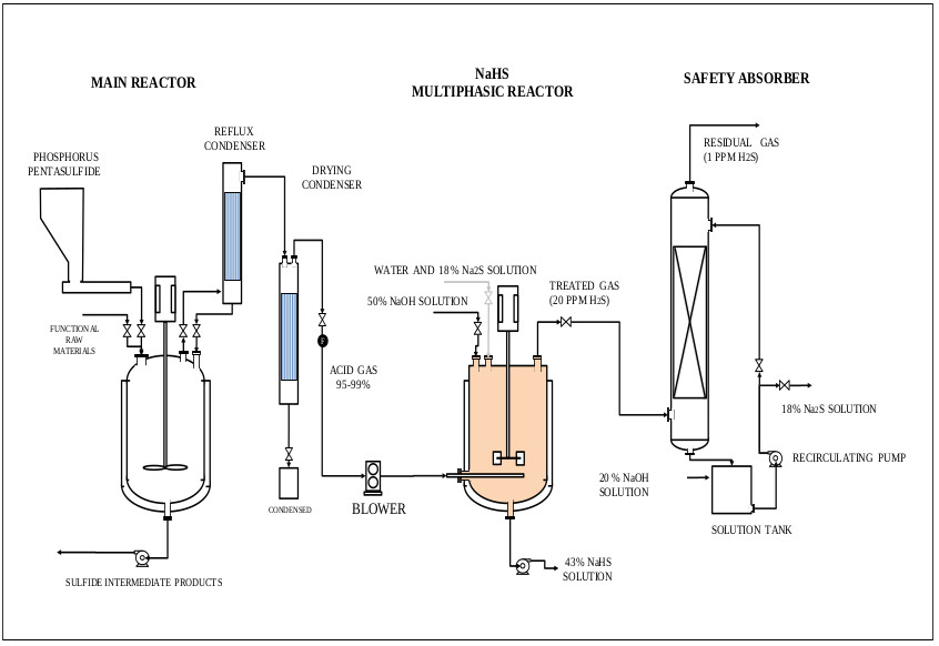
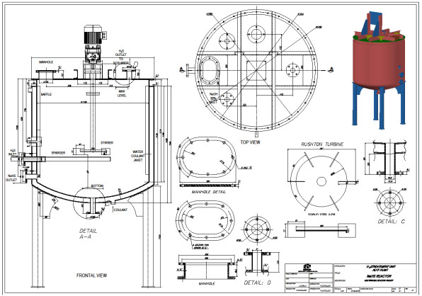
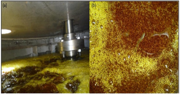
H2S gas of 0.2 vvm (for 4-hour reaction) which is on average that a stable production of H2S is recorded, although the H2S is generated in the ADTF reactor for 6 hours until it is completely extinguished, and the cooling water flow of the system is 1930 L (8.04 L / min). The calculations of this part are not presented. Figs. (17-20) show the internal part of the reactor in full operation, the instrumentation diagram of the industrial reactor, the integration of the reactor within the process of production of dithiophosphoric acids, and the complete design of the reactor respectively.
The gas hold-up (Eg) corresponding to a gas flow of 0.2 vvm, at a temperature of the NaHS solution 43% of 50 oC, pH of 8.5, where the absorption of H2S has decayed, therefore the gas It retains in the reaction mixture and it is observed that bubbles and foams are produced on the surface. The maximum volume displaced is 1397 L (without considering the foam mattress). The volume of the aqueous solution of NaHS with agitation and without gas flow is 1285 liters. Therefore the Eg [84] is: Eg (hold-up) = (1397-1285) / 1397 = 0.0801.
When the pH is greater than 11, there are few H2S bubbles and the foam mattress is not observed. The maximum displaced volume is 1397 L, at this point the H2S bubbles collapse and are absorbed in the reaction mixture, and no gas retention is observed. When the industrial reactor with an impeller diameter of 0.387 m and agitator speed of 1.33 rev / s, works with the 43% NaHS solution at 50 ° C, the viscosity and density of the solution are 0.00624 Pa.s and 1280 kg / m3 respectively. The value of the Reynolds Number (NRe = ND2ρ / μ) [85, 86] is 40860. For a Rushton type impeller with W / D = 1/5, graphically [85, 86] the value of the power number of 5.
The power number (Np) has not been directly measured, however the power consumption of the agitator motor is 1230 Watts, which allows to maintain an adequate agitation, suspension of the crystals and dispersion of the H2S bubbles, for a reaction mixture of 1644 kg. In all forms of the reaction mixture (single phase, two phase and three phase) there is no significant change in power consumption. However, there is a major change in the adjustment of the axial seals of the (packed gland) agitator.
CONCLUSION
In this study, the synthesis of sodium sulfhydrate was carried out from hydrogen sulphide, which is a highly toxic gas and a by-product of the dithiophosphoric acids production process in the Reactivos Nacionales S.A. Company.
- A recovery method has been established and implemented that allowed obtaining sodium sulfhydrate with concentrations higher than 43%, in a semicontinuous form and at temperatures ranging from 50 °C to 55 °C, with an average temperature of 52.5 °C. The temperatures reached are much lower than the temperatures of recovery technologies currently available in the market.
- It is possible to produce aqueous solutions of sodium sulfhydrate from Gas-Liquid-Solid reactions. The conversion of hydrogen sulphide into sodium sulfhydrate was carried out in a stirred multi-phase reactor at 700 rpm, which allows the solids to be kept in suspension, which are mainly made up of sodium sulfide crystals (Na2S.5H2O).
- According to the tests carried out, the conversions of H2S in NaHS obtained in the multiphase reactor are greater than 90%.
- From sodium hydroxide at 50% of commercial grade, 43% sodium sulfhydrates have been obtained, chemical Eqs. (2-4, 8 and 13) explain the process. The reaction medium that promotes the conversion is formed by an aqueous solution of NaHS and Na2S that allows the suspension of the sodium sulfide crystals and the contact with the H2S gas in a multiphase reactor.
- Temperature is a critical parameter in the process. At temperatures below 30°C, the presence of Na2S.9H2O crystals affects gas dispersion, reactor hydrodynamics, crystal distribution, heat transfer and absorption of H2S in the multiphase reactor. At temperatures above 60°C, a low absorption of hydrogen sulphide in the reaction medium is registered and consequently a slow conversion of Na2S into NaHS.
- It has been found in this investigation that the main drawback for the manufacture of aqueous solutions of sodium sulfhydrate at concentrations higher than 40% by weight, starting directly from sodium hydroxide, is the formation of sodium sulfide crystals (Na2S.5H2O, Na2S.9H2O) due to its low solubility of these crystals, it is not possible to obtain sodium sulfhydrate safely and efficiently in stirred chemical reactors.
- To obtain 43% NaHS, sodium sulphide and water with percentages of 34% and 56% respectively are necessary. At temperatures higher than 50 oC, two phases could be obtained, comprising an aqueous Na2S solution and Na2S.5H2O (C2) crystals. At lower temperatures, the combination of Na2S.5H2O (C2) and Na2S.9H2O (C1) crystals will appear, starting the solidification of the system, which is a serious problem.
- The agitation speed in the multiphase reactors (pilot and industrial level) studied allows to adequately disperse the gases and maintain the suspension of the sodium sulfide crystals in the reaction mixture to favor the chemical conversion. The best agitation speeds for the reactants established in this study are: 700 rpm for the pilot reactor and 80 rpm for the industrial reactor.
- The results obtained experimentally in the pilot reactor of 5 liters, provided sufficient information to size the reactor of the industrial type of 1 300 liters of capacity, which is appropriate for the requirements of treatment of the residual current of H2S produced in the manufacturing process of dithiophosphoric acids.
- The proposed process has been integrated into the dithiophosphoric acids manufacturing plant, where it has been possible to recover more than 95% of the hydrogen sulfide in the form of NaHS 43% (around 90% of H2S in the multiphase reactor and plus 5% in the safety absorber).
AVAILABILITY OF DATA AND MATERIALS
Not applicable.
FUNDING
The study was funded by Reactivos Nacionales S.A Company.
CONSENT FOR PUBLICATION
Not applicable.
CONFLICT OF INTEREST
The authors declare no conflict of interest, financial or otherwise.
ACKNOWLEDGEMENTS
The authors wish to thank the Reactivos Nacionales S.A Company for the financial support as well as for making available the infrastructure for experimental development in their facilities and for their decision to solve the problem with the H2S that was finally achieved.

